Eng-Tips is the largest engineering community on the Internet

Intelligent Work Forums for Engineering Professionals

Calculation for beam orientation 4

Status
Not open for further replies.

engtiuser2

Mechanical
Oct 13, 2015
43
0
0
CA
I am trying to predict the position of the beam after it is pushed (vertically up) on one end to a known displacement. The beam was originally supported by 4 compression springs with identical spring constant. The springs are equally spaced under the beam (supported at 1/5, 2/5, 3/5, 4/5 of the length of the beam, both extreme ends are not supported). After one end is pushed vertically up, the beam is expected to be tilted (assuming the displacement of the end is not high enough to overcome the static friction between the beam and the spring support). I would like to know the exact displacement of each spring support. The following are the known parameter: Weight and the size of the beam, the location of each spring support, the friction coefficient between the beam and the spring support, the spring constant and the displacement of the end. Any help/recommendation is appreciated.
 
Replies continue below

Recommended for you

1) are the springs initially compressed ? or an ideal neat fit ? or supporting the weight of the beam ?

2) I think you can better understand the problem by applying a load to the free end, a unit load of 1 lbs?, and solving the beam to determine the deflection of the free end. Then to get the required deflection you factor the load and the resulting deflections.

3) By applying a load you can see that the 4 springs are reacting a direct load and an offset moment. You can then make a assumption as to how these springs react this load, yes?

4) You can then work through the equations of a beam (Shear Force > Bending Moment > slope > deflection) to see if the resulting deflections are consistent with the assumed loads.

5) and iterate.

6) If you're smart you may get somewhere imposing the force/deflection relationship of the four springs. I see the math getting pretty hairy, and you may need to solve underdefined equations (I suspect the problem is singly redundant, which can easily be solved with more math … I'd use the unit load method)

7) Is this work, or a school problem ?

another day in paradise, or is paradise one day closer ?
 
I am old enough to be somebody's grand father, unfortunately I got rusty in this kind of problem (may be statistical indeterminate).. love to go to school again but have no luxury. This is a problem that I see from work.
The springs are compressed by the weight of the beam (I used the term of beam to simplified thing). My interest is the rigid body movement of the beam. The beam will be under translation and rotation. The lifting force will not cause the beam to bend.

Want to get away from hell sooner..lol
 
ok, understand the situation better.

I'd simply apply a load at the tip, and the beam will rotate around the middle of the four springs.
So 4 forces react the moment … F*(2*1.5d + 2*1/3*d/2) = M = P*2.5d … P applied at tip, F reaction in outer springs (F/3 reaction at inner springs).
then deflection of outer spring is F/k, and rotation of the beam is (F/k)/(1.5*d), and rotational translation of the tip is 2.5d*(F/k)/(1.5*d)
total translation of tip is 2.5d*(F/k)/(1.5*d) + (P/4k)
and F = P*(2.5/3.33) = 3/4 P

so your known (input?) deflection determines the force P applied, and the spring reactions, the spring deflection, and the position of the part.

another day in paradise, or is paradise one day closer ?
 
Hi engtluser2

Any chance of a sketch or picture with some dimensions please

“Do not worry about your problems with mathematics, I assure you mine are far greater.” Albert Einstein
 
Hi

Thanks for the sketch, not an easy problem by any standards.
Why can’t you fix one end of the beam and make it a pivot? The big problem is where the beam rotation point is, because if it falls inside the spring support arrangement then some springs will be compressing while others are stretching.
I need to think about this a bit more and it’s a statically indeterminate problem in my opinion.


“Do not worry about your problems with mathematics, I assure you mine are far greater.” Albert Einstein
 
I worked the thread just for remember the old days...The assumptions are; beam is rigid, all springs identical and buckling of springs prevented.

I_SPRING_ON_THE_SPRING_0284_lhluvw.jpg
 
Hi Hturkak, Thanks for sharing the idea. I am still digesting your calculation. There are couple of thing that puzzling this rusty old man and would appreciate if you can shed some light.
2nd line: Assuming R1 is the upward force at first support created by P, should it be simply P/4? Not sure why A is involved.
4th line: The equation looks familiar (like bending stress formula). Can you explain how is it applicable to the beam under rigid body rotation? A link to website with this equation application is helpful.
5th line: It would be nice if I can see where is the axis of the second moment of area (I) and the area. The I in the bending moment equation is for the cross section of the beam, can you explain how line 5 arrived. Thanks.
 
engtiuser2 (Mechanical)(OP) said:
2nd line: Assuming R1 is the upward force at first support created by P, should it be simply P/4? Not sure why A is involved.
4th line: The equation looks familiar (like bending stress formula). Can you explain how is it applicable to the beam under rigid body rotation? A link to website with this equation application is helpful.
5th line: It would be nice if I can see where is the axis of the second moment of area (I) and the area. The I in the bending moment equation is for the cross section of the beam, can you explain how line 5 arrived....

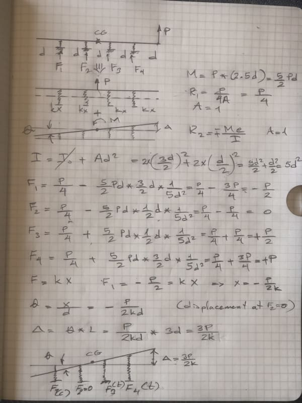
We are at different time zones..I think it is clear, the transfer of force ( P ) to C.G. with Moment M=2.5d* P
The superposition is applied, assuming the beam is rigid.

2nd line = The vertical force P is resisted by four springs . You are right... Eventually Fi= P/4
Famous bending formula is applied : f= P/ΣA +,- (M*y/I) this formula is used to obtain stresses.
In order to find the forces , a similar formula adopted, Fi= P/n +,- (M *y/It)
Assuming identical springs , The force for each spring will be Fi =P/4

4th line: The equation looks familiar (like bending stress formula). Can you explain how is it applicable to the beam under rigid body rotation? A link to website with this equation application is helpful.

The inertia of 4 springs about C.G. is calculated using parallel axis theorem I= Io + A*d**2 Io is zero and area is 1 for this case ,
It=Σ A**d2

5th line: It would be nice if I can see where is the axis of the second moment of area (I) and the area. The I in the bending moment equation is for the cross section of the beam, can you explain how line 5 arrived....

Second moment of 4 springs about C.G. It= 5d**2

And the total area Σ A = 4 (there are 4 springs ).

The same approach is applied to find the resisting forces of each pile under a rigid pile cape. I write (force distribution under a rigid pile cap pdf ) searched the web . one of the link is below...just read page 7 and following pages...

file:///C:/Users/user/Downloads/Two%20Pile%20Group.pdf
 
Hello

If you have a copy of Roarke this is also treated in section 8.5 and table 8.5. There is a example. I recall the figure being just like the one posted. Raorke can be downloaded for free but do not recall the website.

I must admit I would cheat and use the inventor Nastran. I am pretty sure spring constants can be added to supports. But not in the standard stress analysis inside inventor.
 
Status
Not open for further replies.
Back
Top