Continue to Site

Eng-Tips is the largest engineering community on the Internet

Intelligent Work Forums for Engineering Professionals

  • Congratulations KootK on being selected by the Eng-Tips community for having the most helpful posts in the forums last week. Way to Go!

Calculation for Pipe Support Spacing (Span) Tables 4

Status
Not open for further replies.

Dave Thunes

Industrial
Feb 28, 2024
1
I'm attempting to develop some span tables for various pipes we work with. I looked though B31.1 and MSS SP-69 as a reference.

The first thing I tried was duplicating the tables for schedule 40 CS vapor lines (which are all deflection limited). My numbers are close, but not the same, especially when I get to larger bore pipes. Can someone please tell me what I'm doing wrong?

For example, when I calculate the max span for 24" pipe I get 40' where B31.1 and MSS have 42'.

Code:
Pipe Size			24	in (nom)	
Pipe Schedule			40		
Material			A53-B		
Thickness			0.687	in	
Pipe OD				24	in	
Pipe ID				22.626	in	
OD Area				452.4	in^2	
ID Area				402.1	in^2	
Steel Area			50.3	in^2	
Density of steel		0.283	lb/in^3	
Weight of Steel			14.2	lb/in	
			W_d	170.9	lb/ft	
				
Modulus of elasticity	E	29.4M	lb/in^2	
Moment of inertia	I	3421.3	in^4	I=PI*(D^4-(D-2*t)^4)/64
				
Max deflection		x	0.1	in	
Max span		l	482.6	in	l=((384*E*I*x/(5*W_d))^(1/4)
				40.2	ft
 
Replies continue below

Recommended for you

Your max span equation has unbalanced (...) and is missing the conversion factor from Mpsi to psi for E.

I get 38.42ft span
To give a 1" deflection
You have a 0.1" deflection criteria, maybe you mean 1" deflection

I would not be surprised if 5/384 is not the coefficient used to find deflection.
5/384 is the coefficient for deflection of a simply supported beam, but pipe is virtually never simply supported. If the pipe were fully fixed at both supports, the deflection at centerline would be only 1/5th of the simple supported case; 0.2" instead of 1".


I always calculate stress using M = WL^2/10, a beam with partially fixed ends, to simulate a continuous span of pipe over supports.

Are your references showing their deflection equation?

--Einstein gave the same test to students every year. When asked why he would do something like that, "Because the answers had changed."
 
The equation you show is for a simply supported beam where deflection is:

Delta = 5WL[sup]4[/sup]/384EI and when you rearrange you get your eqution with W in pounds per inch and L is in inches.

It is all a matter of what state you consider the ends are. As 1503-44 indicates for a fixed end beam the equation for deflection is:

Delta = WL[sup]4[/sup]/384EI so you get 1/5th the deflection of a simply supported beam.

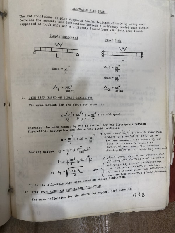
I have a manual from a piping stress analysis seminar at LSU university that recommended using a value of 1/2 the difference between the values of fixed and simply supported which is:

Delta = 3WL[sup]4[/sup]/384EI

It is just a matter of how the codes calculate the deflection. Note that a deflection of 0.1 does appear too small.
 
Here is a copy of the LSU seminar notes regarding pipe spans and point loading at supports:

IMG_1547_bzbx5r.jpg
IMG_1548_cn6z0r.jpg
 
Exactly. 128 <> 384
128 going to look a lot like M=WL^2/10 on a stress based equation.

--Einstein gave the same test to students every year. When asked why he would do something like that, "Because the answers had changed."
 
Lots of good discussion in below thread, 21 years ago!
thread378-49424
 
For my benefit as well, wouldn't you take the nominal thickness of the pipe wall minus the mill tolerance?
 
I suspect standard rolled structural shapes also have a mill tolerance, but nobody reduces the published dimensions in structural design.

--Einstein gave the same test to students every year. When asked why he would do something like that, "Because the answers had changed."
 
TiCl4

That would be the correct way to do it, also including corrosion allowance. If you do a computer stress analysis such as Caesar it will calculate the bending stresses for weight load between spans based on the mill tolerance and corrosion allowance you input, not the nominal wall thickness.
 
Then the pipe weight loads would be 12.5% light before the corrosion occurred. The reduction of I probably causes an increase in deflection greater than the lighter load decreases it.

And doesn't it use nominal thickness for thermal cases?

--Einstein gave the same test to students every year. When asked why he would do something like that, "Because the answers had changed."
 
Just a couple points. First I assume B31.1 is the correct code for your application (on-skid boiler piping, or steam piping)?

Second, remember that span between supports is controlled by allowable stress, and allowable stress is determined by the equations particular to the governing B31 piping code that applies to the piping system in question. Each code has its own set of equations for determining the allowable stress, and each code has its own table of basic material cold allowable stress, but the allowable stress calculation in all the codes are based on the generalized 3D state of stress under combined loadings of weight, pressure, temperature, and seismic. The deflection equations above are based only on My/I which is only in-plane bending stress in tension. You might recall that the stress in a circular pipe under the influence of the combined loadings of temperature, seismic/relief valve thrust/waterhammmer/someone standing on the pipe, internal or external pressure, and weight loads is determined using Mohr's circle (or the generalized 3D state of stress equations, both tensile and shear), of which My/I is just one component. If your pipe is at ambient temperature, with zero internal pressure, and your *only* load case is weight of pipe plus contents, then yes, the base simple beam deflection formula using S=My/I where S is the basic material allowable stress is used to determine allowable span because all the other components of Mohr's circle go to zero.

Point of all this is the span of a line under combined loadings may be significantly less than the span predicted by the simple beam deflection equation.

Most folks nowadays use one of the various piping flexibility software packages to do this kind of work (CAESAR, TriFlex, AutoPipe, etc.) because it is infinitely faster than doing it by hand. Having said that, there are folks who don't like to use that software, so you are welcome to do it by hand and use Mohr's circle.

 
Bookmarked for review.
\Questions: Simple supported (rigid) beam of constant circular cross-section for pipe?
Or are both beam ends "clamped" (restrained) by the physical welded elbows to the two vertical pipes?
Span = hori dist between the two centerlines? Or the hori dist between the two welded joints at elbows?
 
Status
Not open for further replies.

Part and Inventory Search

Sponsor