Continue to Site

Eng-Tips is the largest engineering community on the Internet

Intelligent Work Forums for Engineering Professionals

  • Congratulations waross on being selected by the Eng-Tips community for having the most helpful posts in the forums last week. Way to Go!

Calculation of Foundation Loads for Silo 1

Status
Not open for further replies.

ShawThing

Structural
Aug 17, 2017
46
Hi

I am requiring to calculate the distribution of wind loading forces on a circular silo's foundations which are located on three different pitch circle diameters.
Is the best way to do this to assume a unit value for each location, calculate the moment of inertia of the foundations and use Z=I/y and σ=M/Z to calculate the stress/load at each location. If there are multiple foundations for a given 'y' value then I assume you would divide by that number to get the load at each location. Will this procedure account for the couple in each half of the silo foundations?
Any advice would be appreciated. Refer below for the foundation layout for information.
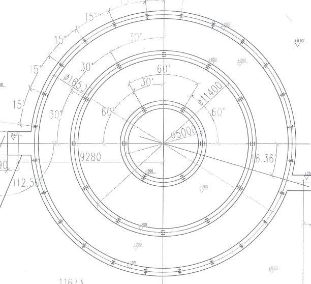

Capture_mrrl61.jpg
 
Replies continue below

Recommended for you

I'm not sure I understand the silo arrangement or your proposed loading.
On a normal silo, the wind loading would be mostly on the shell, and so would presumably wind up in those outer supports.
In the past, I have run into problems designing a tank on concentric foundations like that. Specifically, you can make assumptions about load distribution, but if the settlement or deflection in the foundations isn't uniform, it can throw the loading values off as well. If the silo is stiffer than the foundations, then you have problems.
 
The sketch is unclear.
[ul]
[li]Do the wide flange shapes represent the structure above loading your foundation, or the piles below supporting your foundation?[/li]
[li]Is the foundation 3 independent reinforced concrete rings (very nasty as JStephen pointed out) or is there a continuous slab joining them?[/li]
[/ul]
I hear "silo" and automatically assume granular storage (i.e. non-liquid). Granular storage often results in other odd or non-uniform loads on the foundation if the filling or withdrawal isn't dead centre. Shell vertical loads will be created by the granular friction during filling and withdrawal. Etc, etc, etc.
 
Apologies if the sketch is unclear.
The sketch is a plan view showing the steel support columns. The three circular rings do not necessarily relate to the foundations at this stage. I was proposing isolated bored pier foundations founding on rock for the foundations under each column but you raise some good points in relation to having separate foundations.
I was trying to calculate the distribution of the vertical wind loads on the foundations resulting from the lateral wind loads on the silo. I understand that the outer columns will have higher loads but was interested in the process in calculating the distribution of these loads. I have since realised that the weight of the silo may ensure that no uplift due to lateral wind loads will be possible although this process would be useful to know for similar future situations.
Thanks for taking the time to reply.
 
I don't know if this can help you but the Anchorage Design for Petrochemical Facilities have a good sample on calculation for vertical vessel anchorage system. You can use it to define the forces. That's on page 142 for 1997 edition
 
Obviously the simple solution is to assume the wind load is only carried by the outer ring of columns.

In that case Pmax = 4 M / (N D). In the figure I can see D = 16.5 m and N = 24 columns. Thus Pmax = M / 99. Obviously if M is in kN·m then Pmax would be in kN. This Pmax is for the case where the wind direction is directly through a column. If the wind were blowing directly North in your figure (between two columns) the max load would be very slightly smaller, but you only need the worst case to design your columns or foundation. If you want the individual column loads, then just like a normal moment diagram, the loads are proportional to the distance away from the neutral axis.

This equation is true for a moment applied to equally spaced resistance points on a constant radius. Anchor bolts on circular vessels is the most common use, but columns of a circular vessel is equally valid.

 
Is it all braced up evenly? Sometimes these have bracing omitted in certain planes (to drive under) and that changes appreciably the way the lateral load is driven to the foundation.
 
Status
Not open for further replies.

Part and Inventory Search

Sponsor