Continue to Site

Eng-Tips is the largest engineering community on the Internet

Intelligent Work Forums for Engineering Professionals

  • Congratulations KootK on being selected by the Eng-Tips community for having the most helpful posts in the forums last week. Way to Go!

Calculation of Shear Area for Built-up Section - W-Shape with W-Shape Cap

Status
Not open for further replies.

canstruct12

Structural
Dec 18, 2018
26
Hi all, I am trying to calculate the shear area for a built-up section for input in STAAD.

I have found a number of resources to determine built-up section shear area, but have not bee able to find any guidance on calculation of the shear area for this specific configuration: W-Shape with a W-Shape cap.

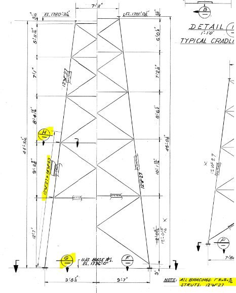
For reference, the W-Shape with a W-Shape cap shape is used as leg of a bent which supports a truss carrying an open channel flume.
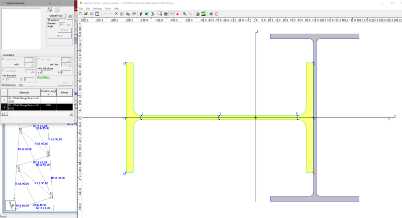
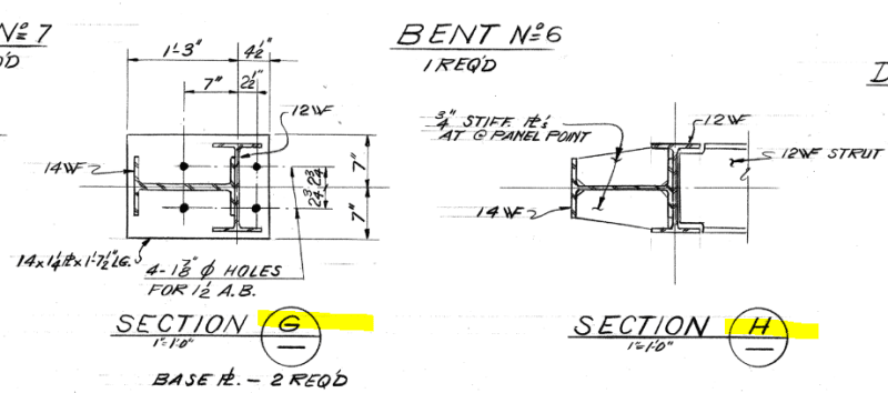
W12X27W14X43_xut4cd.png
5610-C-413_-_W12X27W14X43_Base_Plate_uktvtb.png
5610-C-413_-_W12X27W14X43_rjnebm.png


Thanks, CS12
 
Replies continue below

Recommended for you

Shear rarely governs the design for steel, so my first check would be looking at the beam without the cap as providing the only shear resistance. If more is necessary after that check, then I'd dig deeper.
 
Jayrod12: Thank you, I agree. I was planning to manually input the shear areas for the W12x27 section alone (conservative), and see if there was any failure under that condition. I just wanted to create a model as accurate as a possible (and to know for myself how this would be obtained), but that level of effort may be a waste. More a personal curiosity at this point.

From what I can determine from STAAD, it tends to take strong axis shear area as (d * w) and weak axis shear area as (2/3 * 2 * b * tf)

Keeping consistent with this, I thinking the shear areas for the built-up sections would be
Along W12x27 Strong Axis: W12x27 (d * w) + W14x43 (2/3 * 2 * b * tf)
Along W12x27 Weak Axis: W14x43 (d * w) + W12x27 (2/3 * 2 * b * tf)
 
What do you mean by "shear area"? Are you looking for a stiffness section property to put into the frame analysis, or are you looking for an area to be used in the strength calculation?

Assuming vertical loads in your figures:

If you're looking for a stiffness section property, then I'd recommend adding the shear areas for the 12WF and only one flange of the 14WF. The shear area of a rectangle is 5/6 times the area. So the total would be d*tw for the 12WF + (5/6)(bf*tf) for the 14WF.

If you're trying to calculate the strength then just add the two, so d*tw for the 12WF + bf*tf for the 14WF. That would be consistent with the AISC Spec. methods.
 
1) Agree with jayrod12's response.

2) For whatever direction of load is being considered, your shear area for design purposes is the sum of all of the plate elements (flanges and webs) whose strong axis direction aligns with that load direction. As with ordinary beam webs, we usually assume that all of these plate elements go plastic at capacity.

3) Modelling accuracy likely won't be appreciably impacted by the shear area so long as we're dealing with solid webbed sections.
 
@271828:Thank you

Shear Area in this case refers to the area used to calculate the shear capacity of the member in the strong and weak axes.

When using STAAD and creating a section in their sectionwizard application, the shear area is not automatically generated (other properties are generated) and the reasoning is that there are different methodolgies (see link below)

[URL unfurl="true"]https://communities.bentley.com/products/ram-staad/f/ram-staad-forum/151776/ay-az-values-in-section-wizard
[/url]

@KootK:

1)Agreed

2)Thank you, do you have any reference for this?

In a previous thread on Eng-tips the use of (2/3 * 2 * b * tf) shear area for weak axis shear is discussed, and also the full shear area (2 * b * tf).
[URL unfurl="true"]https://www.eng-tips.com/viewthread.cfm?qid=360926
[/url]
STAAD uses 2/3 * 2 * b * tf , and I was just curious as to where this came from


3)Agreed, I don't believe shear capacity will govern for this
 
The only reference I can give you is the steel design manual. You'll see that it's provisions mostly use the full area as the plastic shear area. It always surprised me that was the case for the flanges of wide flanges in weak axis shear but whatever.

The 2/3 business comes from treating plate elements elastically rather than plastically. So that parabolic stress distribution rather than a uniform one.
 
@Kootk:
Thank you, this make sense to me, and I will regurgitate for my own understanding

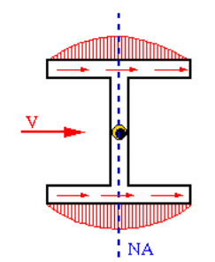
If stress distribution is considered elastic then then it would look like this (and the area under the curve would be represented by 2/3 BxH):

elastic_shear_stress_distribution_i3gsbf.png


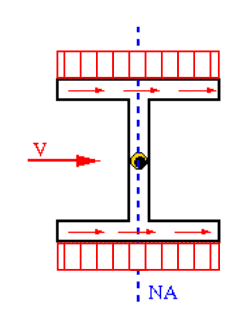
If stress distribution is considered plastic then it would look like this:

plastic_shear_stress_distribution_jwolf0.png


On another note, this is another built-up shape (angles and batten plates creating a C-shape) in the structure I am analyzing (old structure from the 1960s), I think using the elastic shear stress distribution would be more applicable for this shape.

Built-up_C-Shape_yyxeet.png
 
You're most welcome. Regurgitation approved.

With regard to the battened members, how you treat it for shear is going to be a function of the degree of composite behavior that you plan to avail yourself of. If the two members will be expected to behave compositely then the shear response of that composite member is likely to be dominated by the vierendeel truss aspect of that behavior and not the shear deformation of the angle legs.
 
Status
Not open for further replies.

Part and Inventory Search

Sponsor