Eng-Tips is the largest engineering community on the Internet

Intelligent Work Forums for Engineering Professionals

Can a bevel gearbox be used with rotation of housing as well ? 4

sh3rlock.holmes

Mechanical
Sep 24, 2024
8
0
0
NL
Hello Engineers,

My first post here. We are in the process of designing a custom machine, in which power from a motor has to be distributed to 4 shafts, while the axis of the shafts themselves rotate around a central axis. I hope it is clear from the picture attached.

20240924_173512_twpbyt.jpg


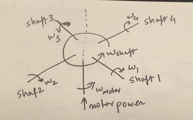
For this purpose, we need a suitable gearbox. At the present moment, we are looking at a 4-way bevel gearbox, (again attached as picture). From the theory I know, this should theoretically work, since the housing of the gearbox can rotate in the central axis, and the shafts can rotate in their axes.

20240924_173559_uyteaa.jpg


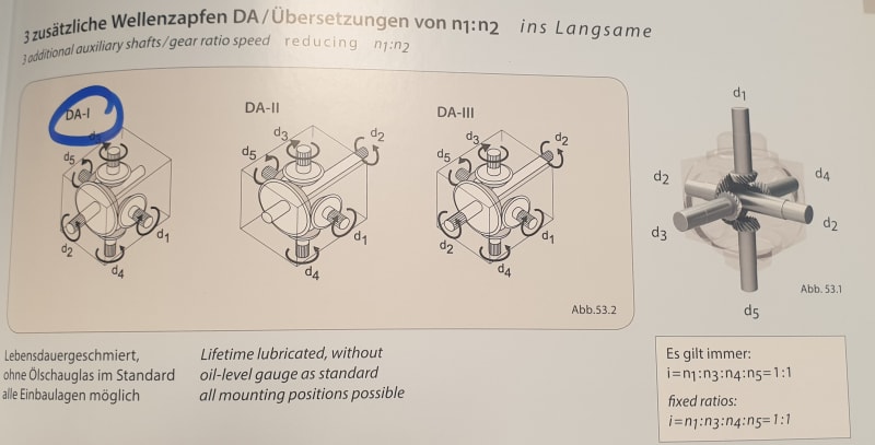
But I think the gearboxes are not designed with such an application in mind. The usual use case is to fix/mount the housing to a stationary body.
So my question is, first of all, do you see any problems with this application, and are there other/special gearboxes that are designed specifically for this purpose?

EDIT : OK I forgot to add a key point. As mentioned before, the 4 shafts and the gearbox housing should rotate about a central axis. THIS ROTATION IS EXTERNALLY POWERED BY A DIFFERENT MOTOR. So basically, the housing of the bevel gearbox will be made to rotate at a constant speed via a different motor, and the initial motor whose input shaft is shown in the picture is used to supply torque to the 4 shafts. This torque control must be independent of the overall rotation, hence we are using 2 separate motors.
Thanks to everyone who commented so far. I'm sorry I forgot to mention this key point.
 
Replies continue below

Recommended for you

It is the difference in the rotation of the input shaft relative to the gear box housing that causes the remaining shafts to rotate. If the gearbox is allowed to rotate freely with the input the output shafts won't. What one could do is add a gear to the face of the gearbox, fix the input shaft to the machine, and then drive the gear attached to the gearbox. This would cause the remaining shafts to rotate relative to the gearbox as the housing turns.
 
Op
I don't know if this will work, all the or part of the Torque and rpm efficiency
Will be lost. Is there any existing designs
With such an un orthodox design.
Take a look a old conventional old style
Differential.
 
In your image, you can rotate the gear box around the D2 shaft axis. This is how q Z-Drive in a tugboat works. The gearbox is suspended by a slewing gear and rotated around the vertical shaft. Steering motors drive the slewing gear.
 
@TugboatEng I think this is what we have in mind. So in your experience/knowledge, we can rotate the gearbox around the D2 axis and transmit torque to the D1 axis without any problems?
 
This seems like a miter box gear manufacturer question. What type of bearings are used will have a lot to do with the allowable axial load that this sustains. How much axial load is involved?
 
Hi Everyone,
After TugboatEng's and dvd's post, we contacted the manufacturer, and they are fine with such an application. For now we will move forward with design. I am sorry that I cannot disclose the full application, as it is a custom order machine and the client doesn't want the design to be out there. Thanks to everyone for thinking about the problem!
 
Here is a case where op has made his mind up.
Another disaster in the making.
With all that mass and moment, no body diagram of the loads and forces.
The only solution will be 0-15 rpm, with very very very light loads. Depending on the bearings and type of bearing
.the strength of the gears for the amount of torque and rpm.
Well an other happy ending
 
First of all, I had never thought about trying it with lego. I think that was brilliant,
MintJulep.
When you tried to rotate the housing counter clockwise, it worked right? You were able to rotate it, for example from 0:23 to 0:27 in the video?
I know I am asking too much, but instead of rotating the housing with your hand, could you add a second motor with a gear that is attached to the housing, so that it drives the housing in the same way as you did from 0:23 to 0:27 ? Probably its a lot of work, but I would be grateful if you post a video with that and report your findings. Completely understand if you don't want to, the idea alone was awesome. I think I will ask our team if we can do this!!
 
@sherlock

You say you need independent torque control.

My Lego already demonstrates that the rotations are coupled, so you can't get independent torque with this arrangement.
 
@MintJulep I think it depends on whether the motor that drives the 4 shafts is in torque control or speed control mode. We want the motor to supply equal torque to the 4 shafts, so in torque control mode.
I understand that the housing rotational speed is coupled to the output shaft speed. However, this relationship is also influenced by the speed of the central motor. In the video, the central motor was rotating at a constant speed if I am not wrong. What I was thinking is, if the housing speed is changed, BUT we still want the output shafts to rotate at the same speed as before, can the central motor's rotational speed be adjusted to achieve this? I am thinking that if the central motor is in torque control mode, it will find a new equilibrium (of course, a point within the operational region of the motor) where the output shafts rotate at the same speed, but the housing speed is different.
I think what we need to really test this is a constant load torque on one of the output shafts. Then we must put the central motor in torque control mode, and then see if the system works when changing the rotation of the housing. I will ask my colleagues if we can do this in lego.
 
Thanks a ton again, MintJulep! Yes, if you also agree that we can get the speeds we want by independent motor control, then I think we can proceed. Although as you said, torque might be up in the air. One of my other colleague suggested that we do a multibody-dynamic simulation of the gearbox. This might be the right move, so we are contacting another company to do the simulations for us.
 
Here some brain storming.
What Precision is required for the entire gear box. Will it need two bearings .
How will it be mounted.

With out the gear box rotating it simple
To calculate from the gear ratios the output Torque and rpm.
However as the gear box is spinning
(Rotating) how does this effect the four pinions. Depending on the direction of the gear box rotation. Clockwise or counter clockwise. The gear pinions are now subject to uneven radial loads.
Yes I not saying this will not work.
But with the corrected, mounting and precision , it could very well work, if the loads are even and compensated.
I agree to remove all doubt a full 3 d simulation could put it to rest.
To achieve the required Torque and rpm a redesign may be required of the gears.
And two variable geared motors may be required to precisely control the rpm and Torque of the d2 shaft, and the gear box.
A redesign or major modification to precisely mount the gear box and to precisely mount a gear or sprocket.
The above Lego build while encouraging does not demonstrate the loads, Torque achieved and how many cycles it will run before failure.
 
Thanks @mfgenggear! Yes, all the points you mentioned are important. We will try and do a full simulation, and then work with the manufacturer of the gearbox to make a possible custom gearbox for us, since off the shelf parts may not have been designed with the additional radial and axial loads due to rotation of the housing.
 
Another thought: I would be very careful to prevent bearing races walking. When a housing is stationary the outer races can be slight clearance fit without much risk of them moving around under load, since the internal and external loads tend to be a consistent direction. If the housing is rotating, then you have the direction of load constantly changing from the perspective of the outer bearing race, and if the race walks in the housing bore it will wear out very rapidly.

If the gearbox design has a press fit on both the inner and outer races of the bearings (e.g. tapered roller bearings) it should not be a problem. If it has ball bearings, spherical roller bearings, etc then the assembly process may dictate some clearance fits.

Or the gearbox manufacturer may not consider this at all. I see all kinds of defective engineering in the low-cost gearbox market. Hopefully your vendor is one of the knowledgeable and thoughtful ones.
 
Back
Top