Continue to Site

Eng-Tips is the largest engineering community on the Internet

Intelligent Work Forums for Engineering Professionals

  • Congratulations SDETERS on being selected by the Eng-Tips community for having the most helpful posts in the forums last week. Way to Go!

Can a Position callout be applied to a circular feature of size (2D element)?

Status
Not open for further replies.

Tarator

Automotive
Sep 20, 2013
176
Hi all,

I do have the following two questions to confirm their answers with mine:

1) Can a Position callout be applied to a circular feature of size (2D element)? (My answer is yes)
2) What is the shape of the tolerance zone, a cylinder or a circle? (My answer is a cylinder)

Thank you.
 
Replies continue below

Recommended for you

My answers are:
1. Yes, because it's a Regular Feature of Size explicitly mentioned in the definition.
2. Cylinder because a cylindrical tolerance zone can include a center point of the circular element being controlled. In addition, there is no mention anywhere of circular (2D) tolerance zones.
 
Tarator, Burunduk,

Other than the argument that the standard does not mention 2D circular zones, why cylindrical tolerance zone?

Thanks.
 
If a position callout is applied to a circular element or cross section of a cone ( as an example) then I would think that the tolerance zone is a 2D circular or circle and not cylindrical.
 
To pmarc's point,

There is nothing in the standard to imply the use of a cylindrical tolerance zone. As a matter of fact, the resolved geometry of the 2D element would be a single center point. In theory, a spherical tolerance zone should be used. The question is up to interpretation without the definition of a 2D tolerance zone. As far as practicality goes, I think a cylindrical zone would win over a spherical zone even if directly contradicting the established relationship between resolved geometry and tolerance zone shape.
 
pmarc said:
Other than the argument that the standard does not mention 2D circular zones, why cylindrical tolerance zone?

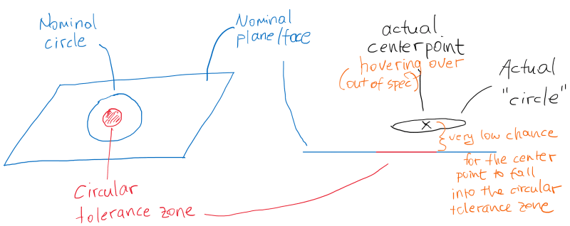
If the tolerance zone was a circle, then almost no actual circle would fall into that circle. The actual circle may not be on a plane. You may have to find a best-fit plane first, then project all the circle point onto that plane. And even then, the best-fit plane and the nominal plane may not coincide. So the actual center point may be hovering over the nominal plane, but never inside the tolerance zone.

1_yixiww.png
 

Jacob Cheverie,

My logic tells me to use a cylindrical tolerance zone because even though a circle is a 2D element, it has an orientation (normal of the plane, on which the circle lies). Just because the actual face may deform, should not push the circle out of spec. I hope this makes sense.

However, since it is not mentioned in the standard. No one (inspector) may interpret it the same way. So the best solution is not to use it.

The reason why I am asking it that I am dealing with a hole that is, nominally, an exact circle on one end of the tab, and a slot on the other end of the tab, and the draft angle is not constant due to the weird tooling die direction. I could apply Profile of Surface to the interior of the hole opening, but then I would like to take advantage of the bonus tolerance, and the mating part that goes into the opening is a cylindrical pin.
 
Well, I would say that the length/width/etc. of the tolerance zone is restricted to the length/width/etc. of the feature.
If the feature is a 2D element then then TZ is a 2D appropriate perfect volume no bigger and no smaller than the feature. "Can a Position callout be applied to a circular feature of size (2D element)"
 
A circle is infinitesimally "short", i.e. it has no depth. That being said, if you define the location of the 2D tolerance zone at some basic "height", general measurement uncertainty would lead to a non-conformance almost, if not always, every single time.

Furthermore, even the thinnest of sheet metal will produce a cylinder when a hole is punched. Most everything has a thickness associated with it. I think the cylindrical zone is the way to go.

As you say Tarator, if the face were to be deformed would the hole be non-conforming? Even if a pin passes through? What was the true intention of the control in that event?
 
My logic as to "why cylindrical" tolerance zone is:
The goal of the position tolerance will be controlling the location of the center point in directions normal to the true position axis, not in the axial direction. So to eliminate the axial direction aspect of the control, the tolerance zone should be cylindrical and not a 2D circle.
 
Tarator, Burunduk, Jacob, J-P,

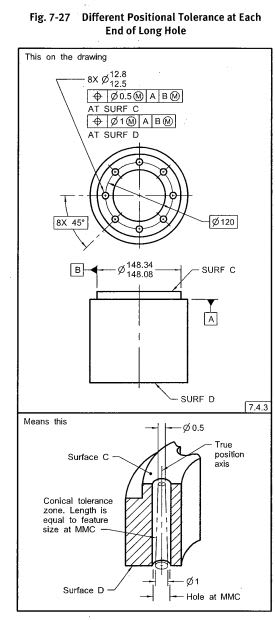
If that's the case, then could you help me understand how the cylindrical tolerance zone concept goes together with what has been shown at both ends of the following feature:

capture_ee1czl.jpg
 
pmarc,
That's a conical tolerance zone. Perhaps one can consider it a collection of infinite number of circular tolerance zones creating a cone. Just like a cylindrical tolerance zone can be thought of as an infinite number of circular tolerance zones forming a cylinder. The center point of the considered circular element can fall into any of those circular tolerance zones or in other words, it can fall anywhere in the tolerance zone cylinder as long as the position control doesn't intend to control the location of the toleranced circular element in the axial direction of the feature it is part of.
 
pmarc,

In your example, the position callouts are applied to a cylindrical feature of size.

In my example, it would be applied to a circular feature of size.

Maybe we can't apply position to a circular feature? Because it is not a feature (a surface or collection of surfaces)? Maybe a circle is not a feature, but an intersection of 2 features? However, it is in the definition of a regular FoS.
 
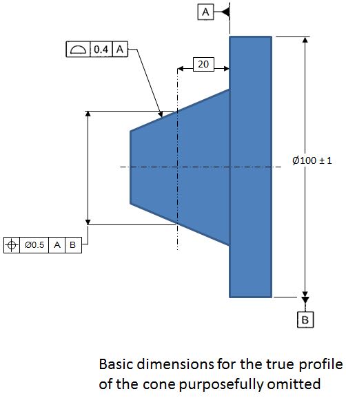
The conical tolerance zone example was not the best choice, so how about this? Why would the concept of the cylindrical tolerance zone by needed in this case?

capture_tyrvui.jpg
 
pmarc,

In your last example, using a gage plane (20 BASIC from datum plane A) ensures that all actual measured points will be on that plane. And if that's the case, the tolerance zone is a circle.

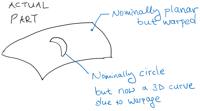
My original example was like this:

4_fzyxcd.png
 
Tarator,
In your example, the first problem to solve would be how to find a center of the hole produced this way.
 

pmarc,

My thought process was to find a best-fit plane for all the measurement points of the actual "circle".

Then, you project all the points onto this plane. The UAME would be a circle (max inscribed circle) on the same plane.

The problem is that this best-fit plane and nominal plane, on which the nominal circle lies, will almost never coincide, which means the part will never be in spec.
 
pmarc -- as much as I love discussing GD&T with you, I wasn't a part of this thread
[wink]
 
J-P,
My apologies. Maybe it's because I subconsciously wanted to see you in this thread ;-)
 
Status
Not open for further replies.

Part and Inventory Search

Sponsor