Continue to Site

Eng-Tips is the largest engineering community on the Internet

Intelligent Work Forums for Engineering Professionals

  • Congratulations IDS on being selected by the Eng-Tips community for having the most helpful posts in the forums last week. Way to Go!

Can a Position callout be applied to a circular feature of size (2D element)?

Status
Not open for further replies.

Tarator

Automotive
Sep 20, 2013
176
Hi all,

I do have the following two questions to confirm their answers with mine:

1) Can a Position callout be applied to a circular feature of size (2D element)? (My answer is yes)
2) What is the shape of the tolerance zone, a cylinder or a circle? (My answer is a cylinder)

Thank you.
 
Replies continue below

Recommended for you

pmarc,
The issue I see with the cone example and the basically located circular element is that theoretically, the center point should be derived from the unrelated actual mating envelope of the circular element. However, the mating envelope that will be used is not allowed to be unrelated - the basic relationship of the plane where the circular element is established to datum plane A imposes a specific orientation and location of the AME to the datum reference frame. This could probably be OK per the 94' version of Y14.5 but questionable per the newer two versions.

If I understand Tarator's case correctly, the circular element is on the intersection (edge) between the hole's surface and another nominally planar surface that is nominally perpendicular to the hole, so I think I understand why he suggests looking for a best-fit plane that may not coincide with any fixed 2D plane on which the tolerance zone circle may be, although because the method involves projection of points from different locations to a single plane, I think that there is nothing in the standard that suggests that this specific method is what should be done in such a case; for example, the edge where the hole meets the planar surface could be projected to a tangent plane to the planar surface (which may or may not be a datum plane). This may also contradict the "unrelatedness" of the AME, but I think the involvement of projection already introduces some non-standardized practise. Another problem with an edge is that it may not be sharp enough to detect its contour unambiguously.
All this assuming I understand the case under question correctly.

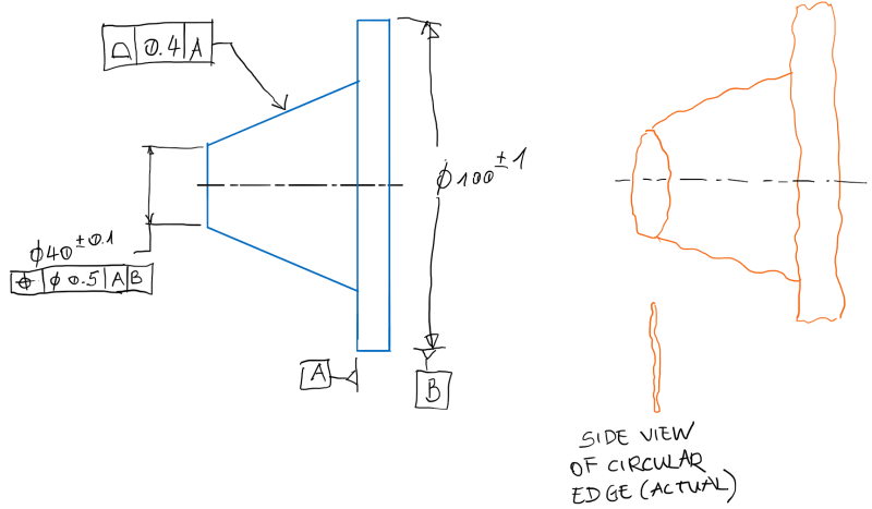
If I may suggest my own example:
An external surface of revolution of some curved, convex shape. The entire surface could be controlled by a generous profile tolerance but the peak diameter could be specified by a size dimension with direct tolerance, and a position tolerance referencing a datum feature which is a bore passing through the length of the feature. The center point of the circular element of the peak diameter would need to be located within some tolerance zone distributed about the datum axis. Naturally since there a no specific axial location where that element should he looked for, the center point should be allowed to fall within a cylindrical tolerance zone. It will surely miss any 2D circular tolerance zone area that may be established at a specific axial location.
 
Burunduk,

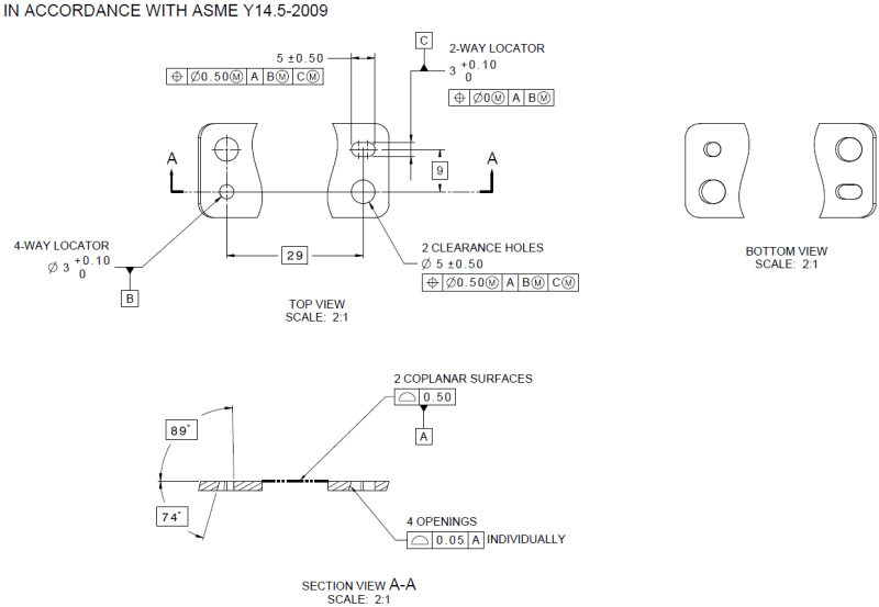
This was my original solution (see image below). All 4 openings are drafted between 1-16° gradually. 2 cylindrical locator pins and 2 screws go into those opening. I am not sure if the drawing represents my design intent. I would rather control them with size tolerance and position than a profile of surface because when you offset the surfaces, the openings won't be a circle anymore because of the variable draft angles. I hope this makes sense. I do have a 3D PDF but I am not sure how to attach it here.

1_znvd7p.png
 
Tarator,
According to the drawing you posted, I think I was correct that you want the size and position tolerances applied only on the intersection edges between the surfaces of the openings and a planar face (datum feature A).
The edges are nominally circular/slot-shaped at the intersection of the openings and datum feature A, aren't they? My interpretation for the reason you think that looking for best-fit planes and projection of points will be necessary is that as a result of the form error of datum feature A, the points on edges will not lie all on the same plane (you will not truly see them straight in section view A-A of a real part), is that interpretation correct or do you have something else in mind? Your description seems to be somewhat different and has to do with "offsetting the surfaces"(?) but I'm not sure I follow what specific issue you seem to detect here.

By the way regarding datum feature A - are these really two separate surfaces or is the gap in the middle created by a "broken view"? If these are separate surfaces it also looks like there are two separate parts.

I don't see how you can avoid using profile of a surface for a complete definition of the part geometry (even if position and size tolerances are utilized), the draft angles need to be controlled somehow. But if you keep profile of the surface in conjunction with direct size tolerances and position, some kind of solution has to be implemented to allow profile to control the form separately of size. There is the dynamic profile modifier in the 2018 version of the standard but since the drawing is per 2009 maybe a note is needed.

 
Burunduk,
I don't share your concern regarding my example. The toleranced element is the center of the actual circular envelope unrelated in location at the single measurement plane. Granted, it is an extension of principles defined for 3D features, but that is all it is, in my opinion.

Also, in your example with the circular element allowed to be anywhere along the axis of the feature I am not sure I see a need for a cylindrical tolerance zone. Regardless of where the actual peak diameter falls axially, isn't the 2D circular position tolerance zone allowed to take the same axial location.
 

Burunduk,​

Burunduk said:
My interpretation for the reason you think that looking for best-fit planes and projection of points will be necessary is that as a result of the form error of datum feature A, the points on edges will not lie all on the same plane (you will not truly see them straight in section view A-A of a real part), is that interpretation correct or do you have something else in mind?

Your interpretation is correct.​

Burunduk said:
By the way regarding datum feature A - are these really two separate surfaces or is the gap in the middle created by a "broken view"? If these are separate surfaces it also looks like there are two separate parts.

It is one part, but 2 separate tabs/flanges, hence 2 separate surfaces. I just cut the guts of the part out as it is irrelevant for the discussion.​

My intention was to use the Profile callout for the orientation (wrt datum A) and the form of those 4 openings. The size and location would be controlled by the size tolerance and the position callouts.
 
pmarc,

How about this version of your example? How would you interpret the tolerance zone? The actual element may look like a closed 3D curve. How do you find the center point? What is the shape of the UAME (circle, cylinder)? What is the shape of the tolerance zone of the position tolerance?

1_fsapvh.png


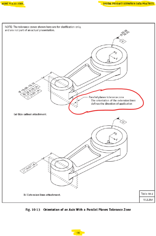
I think for any 2D feature (circle or 2 parallel lines) you need to introduce a supporting plane (gage plane, intersecting plane, etc.). For example, the length size of a slot? How can you find it without intersecting the two half-cylinders with a center plane? And wouldn't the tolerance zone of the position callout applied to it 2 parallel planes? See this image I found:

2_y6bzyn.png
 
pmarc,
The actual circular envelope will be unrelated in location from datum axis B, but doesn't the single measurement plane restrict the circular envelope to be parallel to datum A and offset by exactly 20mm from it?
Are you saying it is OK because it's an extension of principles of a concept that was developed only for 3D features, and since a 2D element is not able to be fully "unrelated" without being ambiguous we can ignore the part of the definition that says "not constrained to any datum(s)"?

Yes, I think it is quite safe to count on the fact that users of the standard will ignore portions of what's written there because most users are pretty good at it and actually ignore more portions than they pay attention to anyway ;-)

Regarding my example, if the 2D tolerance zone should chase the center point wherever it goes, wouldn't it be more straightforward to unite all those possible locations into one cylindrical tolerance zone? Especially considering that a cylindrical tolerance zone and two parallel planes tolerance zone are the only ones described in the standard for the position geometrical characteristic (resolved geometry interpretation). Consistently, where 2D tolerance zones are described in the standard, they are intended to control each element of a feature separately - in separate cross-sections. The separation to different cross-sections seems meaningless in the case of a single controlled element.
 
Tarator,
I'm with you regarding the cylindrical tolerance zone, but frankly when it comes to the interpretation of a tolerance applied to a circular edge (intersection of surfaces), I don't think that anyone will be looking for best-fit planes to find the most circular projection of the edge contour unless you somehow make it explicit on the drawing (and then it might be a very difficult task technically). There is also nothing in the standards that may instruct them to do something like this (I'm mostly familiar with Y14.5 but I bet with high confidence that it isn't covered in the mathematical definition or any of the Y14 standards). The best-case scenario is that the manufacturing unit/QA department/vendor will try to project the contour of the edge of the hole on datum plane A. In the less optimistic and perhaps more realistic scenario they will rest it on the opposing face of datum feature A to make the controlled side visible for an optical measurement system and what they will detect that way is the projection of the edge on the tangent plane to the face opposing datum feature A (or any plane parallel to it).
 
Tarator,
Your modification of my example is something I would not recommend to do in the first place. One of the reasons why would be exactly the picture in orange; if the as-produced edge is a complex 3D curve (which is quite likely to happen), how would its size requirement be even verifed?

In my example that problem does not exist because the measurement plane for the size and position requirements of the 2D feature is clearly defined.

Burunduk,
The actual circular envelope will be unrelated in location from datum axis B, but doesn't the single measurement plane restrict the circular envelope to be parallel to datum A and offset by exactly 20mm from it?
Are you saying it is OK because it's an extension of principles of a concept that was developed only for 3D features, and since a 2D element is not able to be fully "unrelated" without being ambiguous we can ignore the part of the definition that says "not constrained to any datum(s)"?

Yes to the first question. Partial yes to the second. What I am saying is that because the requirement applies to a circular element in a single clearly defined plane the only meaningful degrees of freedom making the circular envelope unrelated are two translations.

Regarding my example, if the 2D tolerance zone should chase the center point wherever it goes, wouldn't it be more straightforward to unite all those possible locations into one cylindrical tolerance zone?
I don't think it would really matter. Regardless if someone interpreted this as a cylindrical or circular tolerance zone, the object of verify would be a 2D feature with no length in axial direction.
 
Burunduk,

I agree with you. No one would bother with a best-fit plane.

To me, it seems like 2D elements are not "real", they are more like construction geometry. In pmarc's example, the feature is a cone. The called out circle is a construction geometry. In my example, the feature is an irregular shape, the circular edge is a construction geometry (intersection with datum A). In a slot, the 2 parallel lines are intersection geometry with the center plane of the width. The feature is a pair of semi-cylinders. So my point is 2D elements need to be supported by a plane. This plane can be called out or implied by the dimension line or viewing angle. In my example, the plane is implied by the viewing angle (perpendicular to the paper), and the supporting plane is the planar surface (which does not have to be a datum feature).
 
Status
Not open for further replies.

Part and Inventory Search

Sponsor