Continue to Site

Eng-Tips is the largest engineering community on the Internet

Intelligent Work Forums for Engineering Professionals

  • Congratulations cowski on being selected by the Eng-Tips community for having the most helpful posts in the forums last week. Way to Go!

Can I model this connection as a simple connection? 3

Status
Not open for further replies.

Kom3

Structural
Nov 20, 2019
37
Hello all,

I have an existing frame as seen in the attached image. Under dead load, the column is overloaded due to weak axis bending. However, if I model the beam as pinned to the column, the bending in the column decreases quite substantially. The bending in the beam goes up since it is now a simple connection but is still underutilized. Would it be okay to model this connection as pinned? For context, this is a solo pipe rack. It is a frame in the transverse direction and an inverted pendulum in the longitudinal direction (not connected to any other frames/bents).
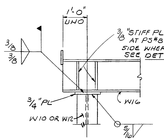
Connection_detail_tcrtzr.png


Thanks!
 
Replies continue below

Recommended for you

The 3/16 field welds seem to be the weakest element in the connection. I suggest to evaluate the capacity of the welds and model the joint as partial moment connection. Also, you may conduct a field inspection (by NDT), if the welds are already cracked, then it is a pinned connection.
 
The length of both the W16 beam and W10 or W12 column are factors. As they get longer (within reason, of course), assuming a pinned connection becomes more reasonable.

Also, the less the W16 deflects under load, the more reasonable a pinned connection assumption becomes.

This will be a judgement call.

What are the beam/column lengths and beam deflection?

[idea]
 
OP said:
It is a frame in the transverse direction and an inverted pendulum in the longitudinal direction (not connected to any other frames/bents).

You're saying that this is a frame in the plane of the page of your sketch, right? If so, I don't see how you could rationally say both of these things at the same time:

1) The joint transfers moments for lateral;

2) The joint does not transfer moments for gravity.

We actually do do this for a system termed flexible moment connection (FMC) but:

3) I think that's BS too and;

4) This doesn't look nearly as flexible as what we do in FMC (mostly clip angle stuff).
 
If the connection can transfer moment, it will. If you're going to count on it to act as a pinned connection in order to make it work (not overstress any components), there will need to be a moment release somewhere in the connection to make that condition a reality.

Rod Smith, P.E., The artist formerly known as HotRod10
 
Kom3:
Is this an existing frame, or one yet to be installed? It looks to me like the columns should be rotated 90°, under the beam, if you want the frame to act like you say it should, as a rigid frame in the plane of the paper. As drawn, it has a fairly weak moment connection btwn. the column and the beam. Your detail is susceptible to the 5/16” fillet welds ripping at the column flg. tips and cap pl., under any lateral load moment., in the direction this moment is needed. Perpendicular to the paper the whole frame just leans a little.
 
I like the approach of retired13. I think you'd first want to establish the capacity of the two field welds that connect the bottom flange of the W16 to the top plate. These can't carry the full fixed-end moment of the W16, so the column may never see as much moment as your model indicates.
 
Need to get my eyes checked. Two people have commented about the 3/16 welds, but they look like 3/8 to me.

I take it the concern is for lateral loading, because if the W16 can span simply for the gravity loading, there is no issue there.
 
kipfoot, it sounds like you are suggesting that it's ok that the 5/16" welds break. Please clarify.

Rod Smith, P.E., The artist formerly known as HotRod10
 
hokie66, I think the comments were regarding the 5/16" welds between the column and the 3/4" cap plate, not the 3/8" welds between the cap plate and beam.

Rod Smith, P.E., The artist formerly known as HotRod10
 
It may not take a lot of weld strength to equal the weak axis strength of the W-sections although no exact sizes have been shown. It looks like the intent was a fixed connection because of the 3/4" cap plate with 3/8" stiffeners (or is that 3/16 stiffeners?). That's a lot of plate for a pin.

Thanks Hokie-I was looking for the 3/16 myself but could not find it.
 
Kom3, does your model that results in an overstress of the column account for the flexibility of the column? As detailed, the beam is fairly well 'fixed' to the column, but the connection as a whole can rotate, resulting in the beam carrying more moment internally and transferring less through the connection to the column. Unless the column is extremely short or braced close to the connection, it will flex and the load moment will be shared between the beam and the column based on their respective stiffnesses (moment of inertia / unbraced length).

Edit: This assumes that the beam is loaded after the field welds are completed. Whatever loads are applied before the the field welding will generate very little moment in the column (just what's generated by any eccentricity in where the beam contacts the cap plate).

Rod Smith, P.E., The artist formerly known as HotRod10
 
If you model it pinned at the top, how is the base plate modeled in the direction of the frame. I assuming the baseplate is fixed in both directions at this time.
 
Thanks for the catch, I do need a better pair of glasses, and a slower finger. I did notice myself, but lazy to correct. Back to the topic, the 3/8 field weld was the beam-column connection weld, one on each side of the beam and column end plate interface, whereas the 5/16 weld was assembly weld (connecting the column and its cap plate) continuous around the column-plate interface. The 3/8 beam-plate connection is much weaker than the 5/16 plate-column connection. It is quite obvious that this connection wouldn't be qualified as full moment connection, it could had been modeled as pin in the original design, however, if the welds remain intact, in my opinion, there is some moment capacity in that joint can be utilized, or to be considered. The OP is evaluating an existing frame, not a new design.
 
Engineers, my my. Please don't confuse stiffness/analysis/load with capacity. Two different things, folks.

The concern here is that there is SOME rigidity in the connection.
The two flange tip field welds have a set capacity.
The beam end WILL rotate under load and thus drive some bending moment into the column.

The question here is really a question of when will the column buckle under moment compared with when the weld will tear under moment.
The OP said it is failing under load when assumed fixed. So there is a serious concern here and just assuming a pinned connection is very questionable.

The rotation/stiffenss of a connection with flange tips welded would be affected by the size of the beam flanges and how they will warp under bending moment.
A very difficult analysis - short of a full finite element analysis check.

So as you apply load to the beam:
1. The beam end will rotate.
2. The rotation will warp the flanges and stress the flange tip welds.
3. Some amount of moment will get through the joint to the column.
4. If that moment is high enough, the column might buckle...you've got a big problem.
5. If the flange warping and flange tip welds are strong enough, the moment into the column might cause failure....same big problem.
6. If the flange warping and flange tip welds are not stronger than the column failure moment, then the column won't buckle/fail but the welds might....you've got a big problem.
7. So unless you can do a full technical analysis of the connection (moment/rotation/warping/FEM whatever) you should do a bracketed, conservative design.
8. Bracketed conservative design - assume the connection is fixed and design all the elements....then assume pinned and design all the elements...then use the most conservative of both.


One other thing...

Those flange tip welds will see an irregular stress magnitude along their length due to those vertical stiffener plates.

Another somewhat complex analysis.

 
I'd feel fine calling this pinned (0 fixity) if I checked two things. 1. With the joint modelled fixed, are the welds strong enough to resist the moment, so that there is no brittle failure? 2. With the joint modelled fixed, take the lateral deflection of the column and add it to the pinned model (to capture p small delta effects). Otherwise, this system has the ductility to behave how you want it to.
 
I strongly disagree with considering this connection as pinned if it less conservative than a moment connection which it seems to be.

If ever in doubt the JAE suggests and ensure it paases in both extremes. That is conservative and is my approach when in doubt.

Though in this case I'd expected the relative atiffnesses to mean that the connection is more fixed than pinned.
 
As much as I like the (somewhat) complex theoretical analysis, I prefer @canwesteng's method to check the gut. Alternatively, throw in a knee brace or stiffen up the weak-axis of the column.

But...dang...a 3/8" field weld in the overhead position is a tough and expensive weld to do!
 
skeltron said:
...a 3/8" field weld in the overhead position is a tough and expensive weld to do!

My take is that only the W16 flange tips are getting field welded, and assuming the 3/4" PL is wider than the W16 (is sits on a W10 or W12 column), it is NOT an overhead weld. But still multi-pass weld.
 
Status
Not open for further replies.

Part and Inventory Search

Sponsor