Continue to Site

Eng-Tips is the largest engineering community on the Internet

Intelligent Work Forums for Engineering Professionals

  • Congratulations cowski on being selected by the Eng-Tips community for having the most helpful posts in the forums last week. Way to Go!

Can I model this connection as a simple connection? 3

Status
Not open for further replies.

Kom3

Structural
Nov 20, 2019
37
Hello all,

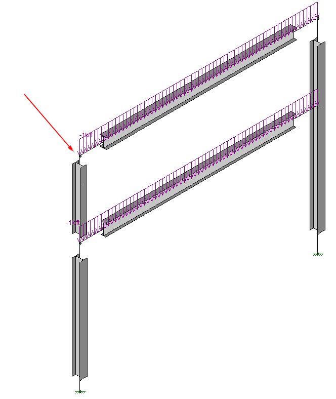
I have an existing frame as seen in the attached image. Under dead load, the column is overloaded due to weak axis bending. However, if I model the beam as pinned to the column, the bending in the column decreases quite substantially. The bending in the beam goes up since it is now a simple connection but is still underutilized. Would it be okay to model this connection as pinned? For context, this is a solo pipe rack. It is a frame in the transverse direction and an inverted pendulum in the longitudinal direction (not connected to any other frames/bents).

Connection_detail_tcrtzr.png


Thanks!
 
Replies continue below

Recommended for you

@bridgesmith: I was trying to express a corollary to your initial post, that if a connection can't transfer moment, it won't. I don't want to make a judgement about whether it's tolerable if a weld begins to yield, but when you're trying to interpret your model results, it's important to recognize that the connection may fail before the column.

FWIW, I was referring to the 3/8" weld in the detail, and Ron247 makes the fair point that it may have been proportioned to be equivalent to the column capacity.
 
The key to your problem is properly modeling it.
The field welds are indeed 3/8" per your sketch, not 3/16". And since this is existing, check the column for an applied (limiting) moment, from all causes (dead plus lateral, applying proper factors depending on how you are checking it - ASD or LRFD) at the top of column equal to capacity of the welds. The capacity of the welds along the frame line, which is at the plane of the paper, should be the moment capacity of the welds. The flange of the beam will probably be stiffer than the welds since I see vertical stiffeners. You did not tell us about the column base conditions. Important to model the base according to how it was detailed too.
Just trying to guess at how the designer designed this, he probably designed the system as a frame in the plane of the paper, but designed the welds to satisfy the moment he obtained from his analysis and cantilevered perpendicular to the frame.
 
kipfoot said:
I don't want to make a judgement about whether it's tolerable if a weld begins to yield, but when you're trying to interpret your model results, it's important to recognize that the connection may fail before the column.

My concern is that there is a risk the weld will fracture, which would generally be considered an unacceptable failed condition. Not knowing the experience or mindset of some of those posting, or someone else who might read the thread, I wanted what you were saying to be clear, so there would be no misunderstandings.

As to the analysis, I would think an FEA may not be necessary. I would start with a basic moment distribution analysis, which assumes the connection fixed, but the beam and column flexible. That should give a fairly good approximation of the moments in the beam and column (including moments at the base of the column if it's a fixed connection). Then you can check the welds, etc. for the moment at the connection.

Rod Smith, P.E., The artist formerly known as HotRod10
 
I haven't gone through all the replies here so sorry if I am repeating someone......but if it was me.....I'd model the (complete) system (with stick elements) and see what moment you get there and check the connection for it. I don't know how long the post/column is.....but you'd likely develop a minimal moment there.

 
Is there a way to rationalize this as a self-limiting condition? Once the W16 is done deflecting and bowing the column, it begins to provide fixity to the end of the column and thus reducing its effective length. Tough analysis - I know.
 
Hello everyone,

Thank you for the responses.

Hopefully this answers everyone's questions. The bottom is treated as fixed. The beam span is 30', the total column height is 27' and the upper column on the left is 10'. This structure is built in the 70's. and the second level was added in the early 90's.

My initial question was whether or not I can assume the formation of a plastic hinge near the connection so it would be considered pin in the model. The maximum moments occur at the top and bottom. Buckling should not be an issue since the bending is weak axis; although the welds itself is worth a check. I am currently leaning towards adding a knee brace if there is no obstructions in the way.

Thanks,


frame_detail_ngvfqf.png
 
Kom3 said:
My initial question was whether or not I can assume the formation of a plastic hinge near the connection so it would be considered pin in the model.

The short answer is no. A plastic hinge is not a pinned connection. It experiences plastic rotation at the plastic moment of the section.

In bridge design, the formation of a plastic hinge under the design loading condition would typically be considered failure and not acceptable. It's sometimes acceptable for the design seismic loading, with the assumption that the component will be replaced if it yields during the earthquake. I'm not sure if it's the same under your governing code, though.

I don't believe you'll get plastic deformation at connection, but if the weld is the weak point, it could fracture.

The diagram of the frame you posted appears to be a model for a structural analysis program. If so, what does the output tell you about the moments? If you're asking about the fixity of the connections to use in the model, I'd say the connection (at the top corner nodes) shown in the OP would have to be considered fixed. If the column end cannot rotate significantly relative to the beam, without breaking something (which looks to be the case), then it's a fixed connection. If you want it pinned, you have to provide a way for the beam end to rotate without bending the column (a moment release).

The only way I could see accomplishing a condition that could be considered pinned, with a welded connection, is to possibly weld the column only along the web of the section and trimming the flanges so they are clear of the cap plate under all loading conditions. I wouldn't even do that without looking closely at the deformation of the welds when load is applied to the beam to ensure they won't fracture.

Inserting a compressible bearing pad and bolting the connection together is the way to accomplish a pinned connection with far less uncertainty.

Rod Smith, P.E., The artist formerly known as HotRod10
 
@Kom, in your model are you inputting the unbraced lengths and effective length factor (k)? I ask because I expect that if you change from fix-fix to fix-pin that while your forces decrease, the compression capacity decreases significantly and based on your loading may be a new issue. For example a 10' tall W10x12 with fix-pin using A36 (1970's) has a compression capacity of approximately 5.16 k and kl/r is greater than 200, whereas a fix-fix/translation allowed column has a compression capacity of 15.8 k.
 
Thank to BridgeSmith clearing the misunderstanding on "plastic hinge".

kom3 said:
[Under dead load, the column is overloaded due to weak axis bending.]

Any thoughts/comments?
 
Aesur said:
or example a 10' tall W10x12 with fix-pin using A36 (1970's) has a compression capacity of approximately 5.16 k and kl/r is greater than 200

Wait, what? l= 120 k= .79 . Kl/r = 151 . pinned-pinned

What tipped me off was that five or so 2x4's have this capacity.

 
XR250 said:
Wait, what? l= 120 k= .79 . Kl/r = 151 . pinned-pinned

I said fix-pin, which has a recommended value of 2.1, how would pin-pin work in this case for the column - it's unstable unless braced. Also where did you come up with 0.79 for k? Fix-pin/no translation is 0.80, maybe that is what you meant? In this case there is nothing keeping the column from translation, only rotation and the original poster said fixed or pinned, so the only options are k = 1.2 for fix base - fix rotation with translation allowed top (fix-fix) or pinned - which would be fixed base and pinned top (rotation and translation allowed) k = 2.1. So for this, L = 120", K = 2.1, r = 0.785 therefore KL/r = 321.

Edit - Further explanation: by fix-pin I am referring to the fact that at the bottom of the column it is fixed, no rotation and no translation, however at the top the "pinned" condition the OP appears to be referring to would result in a free condition, rotation and translation allowed, (inverted pendulum mentioned).
 
Can you put a single stiffener (ea side) in line with the web?... more of a pin?

Dik
 
I'll try to evaluate the limiting moment capacity of this joint (Mc), either the pair of 3/8 welds or the column will control, then model this connection with rotational spring with the constant equal to Mc/Θ, and run the program again to see whether any other thing would have failed under this scenario.

Besides gravity load, don't you have lateral load cases? Was the beam acting like a tie rather than load carrying element? How the columns are supported at base (fixed, pinned)? Was the long column an original design, or replaced after upper level addition? Too many factors may have effects on the depth your problem. People need to know more in order to offer judgement call, "yes" or "no".

I am still curious on the phenomenon that the column has failed under dead load case alone. If there is no mistake in your inputs, then the previous modification design is questionable. You should have someone check your work before moving too far, and work with a senior engineer who has knowledge on design practices and codes at the 70s and 90s.

Let us know your finding, as it would be quite interesting and educational.

 
The connection was clearly designed to transmit moments and approach a fixed connection.
Can you change the connection to more closely appriximate a pinned detail?
As has been said above, if it can pass moments to the column it will, if it can't it won't.
If it is somewhere in between fixed and pinned and you need to define where it actually is, more research or testing is needed.
Changing the model to suit the answer you want is the defintion of unprofessional and dangerous engineering.
Facing up to the situation is where you need to go.
If it fails as a fixed connection the ONLY things you can do is to bring your model closer to the actual reality or bring the actual conection closer to the model that works.
 
IFRs said:
Changing the model to suit the answer you want is the defintion of unprofessional and dangerous engineering.

The OP is to be applaud for bringing up this question.

Since this is an existing structure added in, and survived, since the 90's, I wouldn't suspect the design, but to assume the connection was designed as a partially restrained joint, that all elements satisfied the code specified strength requirements at the time of design, and have behaved accordingly. Although the column and beam can survive under pinned assumption, the present design task may add more load while the joint (in reality) continues to absorb the induced reactions (increased moment in the joint as it is not truly a pin) until something breaks. Yes, change the connection details to fit your assumption is a viable, probably an easier, solution, but could be costly in construction. The designer needs to carefully weigh the pros and cons.
 
Aesur said:
I said fix-pin, which has a recommended value of 2.1, how would pin-pin work in this case for the column - it's unstable unless braced.

Sorry, thought you were talking about in general with top and bottom braced, not this case. My A.D.D. self rears its ugly head :>
 
Status
Not open for further replies.

Part and Inventory Search

Sponsor