Continue to Site

Eng-Tips is the largest engineering community on the Internet

Intelligent Work Forums for Engineering Professionals

  • Congratulations KootK on being selected by the Eng-Tips community for having the most helpful posts in the forums last week. Way to Go!

Can we add MMC modifier on a datum feature estabilished by datum target point?

Status
Not open for further replies.

SeasonLee

Mechanical
Sep 15, 2008
912
Hello All

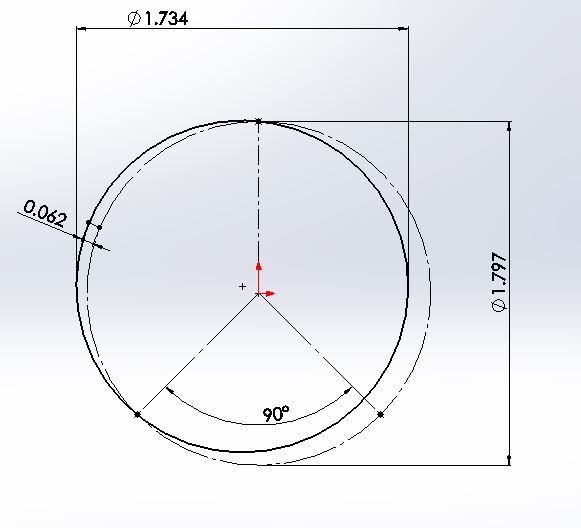
A simple question---Can we add MMC modifier on a datum feature established by datum target points? If yes, what is the VC size and how to build the gage? Please see the attached for details. Thanks

Season
 
 https://files.engineering.com/getfile.aspx?folder=e6a67658-0743-4c62-890c-3f75eeb41be2&file=MMC_midifier_used_on_datum_feature_established_by_datum_target_points.pdf
Replies continue below

Recommended for you

The datum feature will not exceed it's MMB boundary as long as it conforms to the specifications that control it's size, form, location, and orientation. It isn't the objective of a datum targets simulator or "conventional" datum feature simulator to limit the surface of the datum feature from exceeding any boundaries.
 
Yet one calculates that MMB diameter, gives it a number, draws a circle to put the datum target points on.

The feature can exceed that.

The datum feature simulator limits the location of the datum feature from exceeding the MMB. That's its purpose.
 
In the hypothetical case I presented where theres a third datum target opposing the two shown on the OP drawing, contact with all three would not be required the feature at LMC could slip between the pins specified at MMB - since the MMB for datum target points only consists of three points I don't think this violates an MMB based on datum targets. It might not be the job of the simulators to ensure conformance to size or geometric tolerances, but it is its job to reliably establish a DRF. In this case I would say its failing at that job - unless this behavior mimics the mating condition as the mating parts has an identical arrangement of three pins.

This is assuming that some orientation tolerance is added for the 1.797 dia, otherwise all bets are off.

MMB_wyx66w.jpg
 
3DDave said:
The datum feature simulator limits the location of the datum feature from exceeding the MMB. That's its purpose.
The true purpose of the datum feature simulator is to constrain degrees of freedom and allow the establishment of datums.
 
chez311, the behavior you described and illustrated doesn't fail the job of establishing a DRF. It allows datum shift, perhaps more of it than a "conventional" datum feature simulator would allow, but nevertheless, a datum axis is established, and for some cases, this allows sufficient control of the considered features controlled with reference to that DRF.
 
I did not realize they were on a vision quest with a true purpose.

If one builds a fixture to do the inspection the datum feature simulator is to constrain the datum feature. If the datum feature is outside the datum feature simulator something has gone very wrong. That constraint performs the function of limiting degrees of freedom.

chez, thanks for the image. The problem is that were one to look at the virtual condition of that datum feature relative to the MMB datum targets, that virtual condition is larger than the calculated MMB, which is not the case of a conventional fully-enveloping fixture. Worse, there is no general method to determine the amount of excursion in as simple a manner as adding one diametral tolerance to another. In other words, the datum shift that is allowed is not easily predictable and the directions of the excursion depend on where the targets are.
 
3DDave said:
If one builds a fixture to do the inspection the datum feature simulator is to constrain the datum feature. If the datum feature is outside the datum feature simulator something has gone very wrong. That constraint performs the function of limiting degrees of freedom.

There are different levels of constraints of degrees of freedom. The most restrictive one is when the datum feature applies at RFS - no translation or rotation of the datum feature is allowed relative to the datum feature simulator. MMB for a "conventional" datum feature is less restrictive - a less constrained constraint so to speak. Consider MMB for a datum feature defined with datum targets the third level of constraint - the least restrictive. By far not appropriate for every case, but not wrong. In the end, the designer has enough choice to cover the vast majority of cases and is obliged to make the right decision.
 
Yes it is, but I am troubled that you did not understand exactly what that release of restriction entailed and have not commented on the level of difficulty in evaluating it.

Have you got a case for which there is no alternative but this or is this just an academic "why not?" The previous 60 years had not apparently turned up a case to include it in the standard and there seems like no reason to have done so.
 
A simple sketch like the one posted by chez311 can be used to assess the maximum amount of such datum shift. I haven't encountered a case that required such datum feature simulation for a simple cylindrical feature but others did. If this troubles you, you can ask the OP why it was decided to define the cylindrical FOS datum with datum target points in conjunction with MMB.
 
The normal case requires no sketch at all.

Mind that the ordinary case causes a simple part outline shift was well, generally equal to half the diameter; how long to analyze the result of the trefoil offset in that "simple sketch"? Not so simple.

No one has ever encountered a need for this. Any claim to the contrary simply needs to show a practical application for it. That doesn't mean a drawing; that means a detailed tolerance analysis, including the effect of the virtual condition and extra datum shift on the final product, that shows the trefoil behavior being critical to the performance of the part.

 
3DDave, datum shift is not applied when it is "critical to the performance of the part", datum shift is allowed when it doesn't decrease the performance of the part and resembles the conditions at assembly.

Besides, if the size, location, and orientation tolerances that control the datum feature are not too permissive and the feature is produced to them, the "trefoil offset" during simulation of the DRF in practice might not be too significant.
Also, there is always a possibility to have a set of more than 3 datum targets equally spaced on the MMB perimeter. This will further reduce the phenomenon. The standard shows the required minimum of points - which "may" be 3, not less (for the attention of the OP).
A part for which a specification similar to fig. 4-53 is appropriate might be somewhat hard to come by but doesn't seem like science fiction either.
 
Yes. There might be an infinite number of points, like a continuous simulator that hasn't got this problem.

I accept that you have no application where this is advantageous and required.
 
This might be useful in drawings of parts in intermediate production stages, dealing with cast surfaces, when surfaces of rough material need to be used as datum features. Using continuous simulators in such applications is considered problematic.
Most features on a blank workpiece are non-critical, so tolerance zones that are allowed displacement by the shift permitted by this kind of datum feature referenced MMB may be sufficiently accurate for their purpose, even with the additional shift allowed by the "trefoil offset". The advantage is simpler and quicker inspection, aimed at reducing overall costs of production.
 
Ok, as long as you accept the concept applied to lathes by not tightening the three jaw chuck as simpler and quicker.
 
Not tightening the chuck of a lathe is indeed simpler and quicker. Unfortunately, you won't be able to turn anything and the part will fall off. There's a slight difference from using non-adjustable fixture for datum simulation.
 
You can use a drive dog on a lathe. Ta-da - Identical to the fixed location datum targets not in contact with the part.

They usually make good contact at three locations. In fact, just tighten the jaws so that the part is retained; maybe line them up with datum target points.

However your suggestion still fails to prove there is anything but speculative value of a technique that no one uses.

Prove me wrong with one documented case.
 
Lathe dog, 3 jaws chuck, faceplate, whatever. Contrary to the machinist operating these devices, when the inspector doesn't grip the part tightly in the fixture he still may be doing his job correctly (following an MMB specification), and more importantly, he still is expected to stay with all body parts intact at the end of the shift. But there is no "MMB" for fixturing the part for machining.

I don't have a documented case to present, so I described generally one type of case where this scheme might be rational. However, I'm not advocating the inclusion of datum targets at MMB in the standard, because it's already there. If you think it shouldn't be there, it is up to you to prove that no one ever used or might use this.
 
The proof can only be for existence. Therefore it should have been removed until the need was proved to exist.

If MMB cannot be used for machining, then how can the setup be duplicated?

It should not be in the standard. It's too bad the committee failed to investigate all the problems with adding it and not ALSO adding LMB. They really should have done that as well. CMMs can simulate LMB and either this was a gross oversight or the inclusion of MMB was the gross oversight. Non-contacting targets should be specifically prohibited.
 
3DDave said:
If MMB cannot be used for machining, then how can the setup be duplicated?

Do you imagine that a part can be milled while the machine vice "holds" it at MMB?
 
Then it's not depending on the MMB is it? It is RFS in a vice.
 
Status
Not open for further replies.

Part and Inventory Search

Sponsor