Continue to Site

Eng-Tips is the largest engineering community on the Internet

Intelligent Work Forums for Engineering Professionals

  • Congratulations IDS on being selected by the Eng-Tips community for having the most helpful posts in the forums last week. Way to Go!

Can we add MMC modifier on a datum feature estabilished by datum target point?

Status
Not open for further replies.

SeasonLee

Mechanical
Sep 15, 2008
918
Hello All

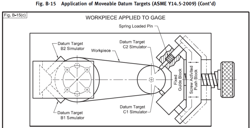
A simple question---Can we add MMC modifier on a datum feature established by datum target points? If yes, what is the VC size and how to build the gage? Please see the attached for details. Thanks

Season
 
 https://files.engineering.com/getfile.aspx?folder=e6a67658-0743-4c62-890c-3f75eeb41be2&file=MMC_midifier_used_on_datum_feature_established_by_datum_target_points.pdf
Replies continue below

Recommended for you

I think the MMB modifier can be added, and I think the datum target simulators should be located on the periphery of 1.797 (MMB) diameter basically spaced 90 degrees.
 
Thanks for the reply, Burunduk.

Datum feature B is a FOS(Ø1.734~Ø1.797), so I think MMC modifier can be used here. I can't find out any similar(MMC) examples from the standards, however Fig. B-15 from ASME Y14.43-2011 is a good datum point simulator on this case, I am trying to figure out how to apply the MMC modifier(VC size) on the gage design. Any thought?
Picture16_fqwuqo.png


Season
 
SeasonLee,
Are you sure you mean MMC and not MMB? The yellow arrow in your attached drawing points on the circled M modifier specified at the datum feature B cell of the feature control frame. This is called MMB in the 2009 edition of Y14.5. Virtual condition is applicable to the holes. Is that what you are asking about?
 
Yes, your are right, Burnnduk. I mean MMB on the gage simulator.

Season
 
Season Lee,
I think the datum targets simulator for B should be similar to how it is shown in fig. B-15 that you posted and the fixed spacing between the pins should be adjusted as I described in my first reply: tangent to a theoretical MMB envelope and with the basic angular spacing required.
The virtual condition boundaries for the holes would be of a size that equals the minimum hole size minus the positional tolerance, located and oriented basically to your datum feature simulators.

Side note: Something about how the part looks - symmetry and shape gives me the gut feeling that you don't really need C to be a datum feature, but instead the entire external contour including the thin side face designated as datum feature C, can be "profiled" with reference to |A|B|
 
What would one expect the inspector to do with the fixture to accommodate the change in radius? More important, what would you expect the machinist to do with the machining fixture?

Suppose that the radius changes as it comes around the part so the AME doesn't coincide with the surface that the target simulators are intended to contact? Should the inspector and the machinist add shims to fill that gap?
 
Just make the fixed pins contact the feature, whatever size it is produced at. This will result in datum shift.
 
This is sort of a weird application for MMB. Yes the standard allows material boundary modifiers applied to datum targets in conjunction with FOS however I would think the typical application would be something like 4-53 where the targets completely surround the feature. Essentially what you have here is simulation of a FOS as if it were a nonFOS since the targets do not completely surround the feature.

I guess some sort of modifier either MMB, LMB or similar must be applied since the datum targets are not basically located and they technically depend on the directly toleranced size of the feature and adjustable location of these targets I think could be even more problematic.

Just make the fixed pins contact the feature, whatever size it is produced at. This will result in datum shift.

I wouldn't call this datum shift - at least not in the traditional sense since you are requiring the part to contact the simulator no matter its produced size. Shifting in this manner actually forces the entire part to move depending on the as produced size instead of allowing float as is typically desired of MMB - this actually seems to be more indicative of RMB than MMB behavior. Its tough to interpret this as there are no examples in the standard of MMB datum targets, especially in this configuration however I do think this is the correct behavior per 2009 though as I think the simulator has more in common with 4-31(c) than a standard FOS simulator. Note that in 2018 this same figure 4-31(c) has been changed to 7-36 and allows separation between the MMB simulator and the part. The latter behavior is probably doable and would actually allow shift but more difficult as 3DDave alluded to.

I do agree with the assertion about datum feature C - it looks to me like it is not driven by function.
 
I can only recall one datum target setup that was driven by function - by specifically duplicating non-inverse datum target features - that is, it was to accommodate an alignment fixture that used precision spheres onto a plane, conical recess, and a v-groove. None of those had an inverse so the only way to identify the actual function was by datum targets, which took out 3-2-1 (not in that order) degrees of freedom.

Other than that all the examples I have seen are not functional representations of what the part will mate with at the next level of assembly, but are conveniences for manufacturing and inspection to enable a consistency to the product handling.
 
chez311 said:
I guess some sort of modifier either MMB, LMB or similar must be applied since the datum targets are not basically located and they technically depend on the directly toleranced size of the feature and adjustable location of these targets I think could be even more problematic.

I agree with this and agree with your remark on how it differs from datum shift. By the way, could this be an example for toleranced dimensions locating datum targets?

"4.24.7 Datum Target Dimensions
The location and size, where applicable, of datum targets are defined with either basic or toleranced dimensions."
 
In order to define a datum feature at MMB, the size of the MMB shall be determinable in first place. This doesn't seem to be the case for datum feature B in SeasonLee's example.

Also, regardless of the reasoning behind usage of this kind of datum target/material boundary scheme I believe that the datum target points B1 and B2 are missing basic linear relationship either in horizontal or vertical direction. Without it, there is an infinite number of configurations of two spherically-tipped gage pins that would satisfy the requirement for 90 basic included angle and for the tips location at the virtual perimeter of the circle of MMB diameter (again, if the MMB diameter was determinable).
 
In order to define a datum feature at MMB, the size of the MMB shall be determinable in first place. This doesn't seem to be the case for datum feature B in SeasonLee's example.

Could you clarify a bit? Is this because the 1.797-1.734 dia is missing an orientation relationship to A?

I believe that the datum target points B1 and B2 are missing basic linear relationship either in horizontal or vertical direction. Without it, there is an infinite number of configurations of two spherically-tipped gage pins that would satisfy the requirement for 90 basic included angle and for the tips location at the virtual perimeter of the circle of MMB diameter (again, if the MMB diameter was determinable).

I'm not sure I follow. I don't have an issue with the part about addition of basic dimensions locating the targets, in fact I think that would clarify some of the confusion on this drawing, but I'm not sure how that jives with the MMB specification. Wouldn't that just fix the location of the two target points at a circle of basic radius a*sqrt(2) where a is this linear distance (either vertical or horizontal from the center of B)?
 
chez311 said:
Could you clarify a bit? Is this because the 1.797-1.734 dia is missing an orientation relationship to A?

Yes.


chez311 said:
I'm not sure I follow. I don't have an issue with the part about addition of basic dimensions locating the targets, in fact I think that would clarify some of the confusion on this drawing, but I'm not sure how that jives with the MMB specification. Wouldn't that just fix the location of the two target points at a circle of basic radius a*sqrt(2) where a is this linear distance (either vertical or horizontal from the center of B)?

Yes, it would, which in my opinion leads to a conclusion that the application of MMB modifier in this case is not the right choice - addition of basic dimension(s) locating the targets makes the MMB modifier meaningless; no basic dimension(s) locating the targets leaves the distance between them totally uncontrolled, therefore makes the drawing specification ambiguous. Basically it's all because only 2 datum target points have been used instead of three.
 
addition of basic dimension(s) locating the targets makes the MMB modifier meaningless; no basic dimension(s) locating the targets leaves the distance between them totally uncontrolled, therefore makes the drawing specification ambiguous.

Even if datum feature B had an orientation specified wrt A? Say a 0@MMC perpendicularity was applied - it wouldn't be acceptable to say the 2x targets had a directly toleranced location (radius) of 0.8985-0.8670 from the center of B with a basic included angle of 90deg - aka the horizontal distance between them would be between 1.2707-1.2261 ? Therefore an MMB tolerance would fix this radial distance at 0.8985 ?
 
In the MMC_midifier...pdf, there is no orientation control possible for datum feature B; these are targets to establish where to restrain the part. They are simply two points at a distance above the given plane; the angle would be important if they were line elements and that would be enough. With points there needs to be a distance. One cannot expect the inspector or fabricator to make some assumption as to how to establish a center point from the part geometry and align the two targets to match, though with 3 points, they can close to a mutual center which may force the part to comply.
 
3DDave,

I wasn't talking about applying an orientation control to the targets themselves, couldn't one apply perpendicularity to the 1.797-1.734 dia? If not, why not?

One cannot expect the inspector or fabricator to make some assumption as to how to establish a center point from the part geometry and align the two targets to match

Thats not what I was saying, at least I don't think I was anyway. I already said that I think adjustable location might be problematic - if the targets were fixed in location either through basic location or the specification of MMB (assuming thats valid in this case - I'm still trying to figure that out, I agree that simulation of a FOS as if it were a nonFOS with 2 instead of 3 points is definitely strange) the part would simply be brought into contact with those fixed pins. I don't think there would be any need to establish a center point from the actual part geometry, unless I'm missing something?
 
You could apply a perpendicularity, but that's not datum feature and would not affect the targets.
 
3DDave,

If the location of targets applied to a FOS are not driven by the material boundary of the feature to which they are attached, then what are they driven by? For example if in Y14.5-2009 fig 4-53 we wanted to reference |A|B(M)| then the fact that the 170 dia feature has no orientation relationship to A is no issue and the MMB would be 170.1 ? What if the 170 dia had a perpendicularity of 0.05(M) wrt A, would that have no effect on the MMB simulated by the targets and the MMB would still be 170.1 ?
 
Please, one figure at a time.

Since the targets would be fixed in space and only contain one planar section they could not detect perpendicularity variation - essentially it would be regardless of feature orientation. The same shift within them would be allowed no matter what the perpendicularity of the remainder of the surface for any size at that plane. Essentially the length of the axis for those targets is zero and perpendicularity is meaningless.
 
Status
Not open for further replies.

Part and Inventory Search

Sponsor