Continue to Site

Eng-Tips is the largest engineering community on the Internet

Intelligent Work Forums for Engineering Professionals

  • Congratulations Danlap on being selected by the Eng-Tips community for having the most helpful posts in the forums last week. Way to Go!

Can we combine hole table and GD&T position tolerance symbol 1

Gaganaut06

Aerospace
May 2, 2023
19
I have a plate which has some 500 hole of different sizes. Our usual practice is to provide a hole table with X and Y coordinates and a plus minus tolerance on the values. Is it possible to provide a positional call out to all 500holes and refer to the hole table as basic dimension. Thanks in advance.
 
Replies continue below

Recommended for you

My apologies for the brevity, but the simple answer is "Yes, you can do that". Do you have any specific concern with doing it the way you described it?
 
My apologies for the brevity, but the simple answer is "Yes, you can do that". Do you have any specific concern with doing it the way you described it?
Thanks for the brevity. My concern is, I have not seen this particular problem in any of standards.
And, usually we give the coordinates wrt to a coordinate system, but if I provide a positional call out I have to provide datums. Can I tell that datum A is XY Plane for the coordinate system, similarly for other datums.
 
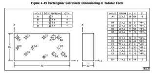
As an example, this is a figure from Y14.5-2018. The related para. 4.6.3 says this:

"4.6.3 Tabular Dimensioning
Tabular dimensioning is a type of rectangular coordinate dimensioning in which dimensions from mutually perpendicular planes are listed in a table on the drawing rather than on the pictorial delineation. See Figure 4-49. Tables may be prepared in any suitable manner that adequately locates the features."

a.JPG
 
As an example, this is a figure from Y14.5-2018. The related para. 4.6.3 says this:

"4.6.3 Tabular Dimensioning
Tabular dimensioning is a type of rectangular coordinate dimensioning in which dimensions from mutually perpendicular planes are listed in a table on the drawing rather than on the pictorial delineation. See Figure 4-49. Tables may be prepared in any suitable manner that adequately locates the features."

View attachment 5315
Thanks a lot for your replay, I was looking at ISO. So now on this drawing I can just provide a position call out right?
 
Right.

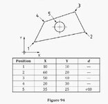
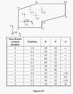
ISO also has some "similar" example figures in their ISO 129-1 standard. The ones below come from the 2018 version.


b.JPG

c.JPG
 
The issue is what are the holes for. Are they functional requirement for assembly or are they lightening holes.
Machining is no problem.
The issue is inspecting them.
In the old days some thing like this would get
Drilled in a fixture, the inspected to functional gage. The was coordinated to a master.
Thousands of parts were identical.
 

Part and Inventory Search

Sponsor