Continue to Site

Eng-Tips is the largest engineering community on the Internet

Intelligent Work Forums for Engineering Professionals

  • Congratulations KootK on being selected by the Eng-Tips community for having the most helpful posts in the forums last week. Way to Go!

Can you skip a projected view on a drawing? 4

Status
Not open for further replies.

Diametrix

Aerospace
Jan 31, 2023
50
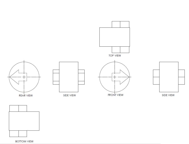
I ran across a drawing where the engineer had front, top and bottom views on the drawing but then next view to the side was the rear view. The justification was that the side view was "skipped". There was not really any room left on the sheet to put it above or below. I couldn't find anything in Y14.3 that would expressly forbid such practice. It just looked really strange to me. Does the standard allow that?
 
Replies continue below

Recommended for you

ctopher said:
The rear view is not projected.
Again, what is this statement based on? If it is not projected, then how is it formed? If it is not one of the principal orthographic views, then it is none of the other views described in the standard. Completely agree with you though on the fact that it obfuscates the drawing.
 
There is a difference between the analytical geometry concept of a 3D object being projected onto a 2D plane and the drawing specific terminology that a projection shows the immediately orthogonal projection from the neighboring view.

The Front and Back views aren't orthogonal projections of each other.
 
3DDave said:
specific terminology that a projection shows the immediately orthogonal projection from the neighboring view
You missed something above in one of my posts. You are wrong in thinking that one projected view is formed from another projected view. Each view is formed from the object/model and Y14.3 standard is quite clear about it: " 5.1 Orthographic Projection: "Orthographic projection is a system of drawing composed of images of an object formed by projectors from the object perpendicular to desired planes of projection"
 
That's the analytical geometry definition of how a 3D object is orthographically projected onto a plane, as opposed to perspective or isometric projections.

It is separate from the idea of projected views which are orthogonal to neighboring views.
 
Based on training and 40 years experience.
I see it this way, if you question how the drawing looks, so will others.
One way to check, take it to a machinist or inspector and ask him/her if it makes sense.

Chris, CSWP
SolidWorks
ctophers home
 
3DDave said:
It is separate from the idea of projected views which are orthogonal to neighboring views.
Again based on what? Can you back up this statement? I provided you a direct quote from the ASME standard that all the drawings are based on, not from some "analytical geometry textbook".
 
Call the committee and ask them to idiot proof the standard.
 
ctopher said:
take it to a machinist or inspector and ask him/her if it makes sense.
That's always a sign of weakness in any position when you ask a direct question and get a response about the number of years you've been doing it the same way. Don't get me wrong, I'm not trying to diminish the importance of experience, but is there a chance we can all learn something new regardless of how many years you've been doing it the same way? BTW, if your litmus test on drawing standards is "taking it to a machinist" more often than not that machinist will tell you to shove any GD&T on your drawing were the sun don't shine. That doesn't necessarily mean that you abandon GD&T altogether.
 
3DDave said:
Call the committee and ask them to idiot proof the standard.
I think the standard is fine as it is. You have to play within the rules set by the standard. So if the standard leaves the room for interpretation, that room should be allowed on the drawing and we can discuss it. However the fundamentals should be clear to everybody involved with no room for interpretation. Such fundamentals (for example, how the projected views are formed) are clearly defined in the standard.
 
"We" aren't learning something new. You are struggling to learn something more than 100 years old.
 
3DDave said:
You are struggling to learn something more than 100 years old.
What can I say, just when I think that I know something its time to revisit the basics again. That's why I come here, so you guys can tell me how its done.[pipe]
 
You asked the question, then question our answers. It's common these days for people to do it how they want, regardless of standards.
Setup your own company standards, and good luck to you. [thumbsup2]

Chris, CSWP
SolidWorks
ctophers home
 
ctopher said:
You asked the question, then question our answers.
There is nothing wrong with that. It is called a discussion, you should try it sometime. To paraphrase your answer, the rear view is not projected based on your opinion. If you read my original question when I started this thread, I was attempting to figure out what the standard says about it regardless of my (or anybody else's for that matter) opinion. When questioning your answer I wasn't trying to cast doubt on what you said but rather to see if you can back it up with anything besides your convictions.
 
Something else I thought of. Does it mean that the example below is an allowable practice? Again, ignore the names of the views. They are there to clarify how I see the views being formed.

Bottom_View_wfiz7x.jpg
 
That is the correct way (3rd angle projection). It is what I mentioned before, it was missing the side view.

Chris, CSWP
SolidWorks
ctophers home
 
ctopher said:
it was missing the side view.
Sorry for the confusion, this example doesn't directly relate to the original question of the view missing. It is about the bottom view being placed below the rear view. Now top view and bottom view are in reverse orientation from each other.
 
So Focused on the 2D drawing and projected views. These days, a 2D drawing is an addition to the 3D model which provides clarity all around of what the part looks like. I agree these views should be projected correctly. I have seen so many drawings with the OP condition above, and the 3D cad software lets the user create these views in any orientation the user wants. Does it cause issues, could, but then the end user looks at the 3D model and then everything makes sense. This is another good excuse to drive to 3D PMI and applying all of the dimensions and specs on the 3D model and do away with 2D drawings.

 
They are reversed because the bottom view is projected from the rear view, the top view is projected from the front view.
Imagine holding the part in your hand and rotating your hand, you see the views.

Chris, CSWP
SolidWorks
ctophers home
 
3rd Angle projection is like unfolding a cardboard box. If one can refold the box so the projection is across each fold then it is fine.

1st angle projection is like rolling the part on the drawing board. If the part could be rolled as represented by the continuity of neighboring views, then the projection is fine.

This latest example would be unlikely to be allowed, not on the grounds of how it was projected, but that it is severely redundant - a separate problem.

Until there is a universal, 100% interchangeable, markup system that is free and has a 100% identical interface for every user, 2D drawings will remain in play. Sure, there are vertical silos within companies that are locked into one vendor solution and they can use 3D PMI just fine - but more and more companies are shedding fabrication facilities to the lowest bidder and that low bidder doesn't have compatibility.
 
ctopher said:
They are reversed
I didn't have an issue with the fact that the bottom view was reversed. The question was more about the layout of the views. I understand that you can unfold the "projection planes box" to look like that (again aside from the fact whether it is a good practice or not) and the bottom view will be reversed.

Aside from the fact that it looks really weird to me I can only site this portion of the standard: "6.1 Orthographic views, unless removed as described below, shall be properly oriented to one another based on orthographic projection and whether first- or third-angle projection is used." The bottom view is properly oriented to the rear view in this layout but no longer properly oriented to the top view. I realize that you can interpret it as "adjacent views should be properly oriented", however the standard uses the term adjacent views in many other places but not here. It's pretty weak, but that the best I can come up with against such a layout.
 
Status
Not open for further replies.

Part and Inventory Search

Sponsor