Continue to Site

Eng-Tips is the largest engineering community on the Internet

Intelligent Work Forums for Engineering Professionals

  • Congratulations cowski on being selected by the Eng-Tips community for having the most helpful posts in the forums last week. Way to Go!

Can't understand how this design actually works

Status
Not open for further replies.

eli28

Aerospace
Oct 20, 2019
109
Hello,

I looked at an existing design of a linear guiding that is actually working and I couldn't believe it.
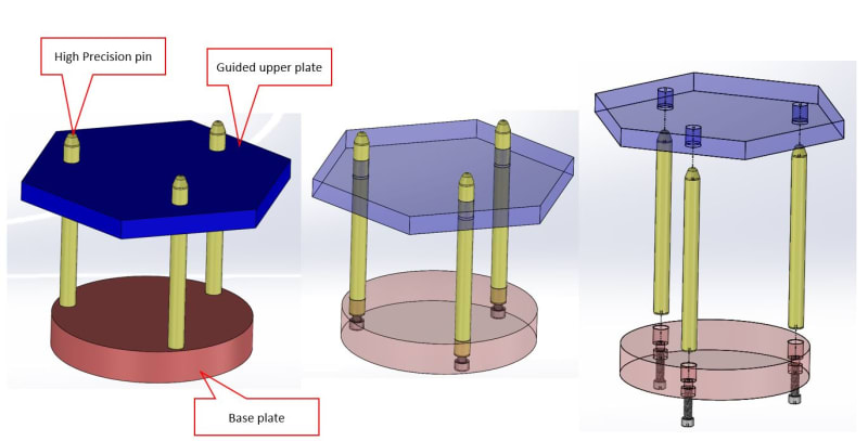
Here is a picture of the design concept so you might better understand :
1_foxe3i.jpg


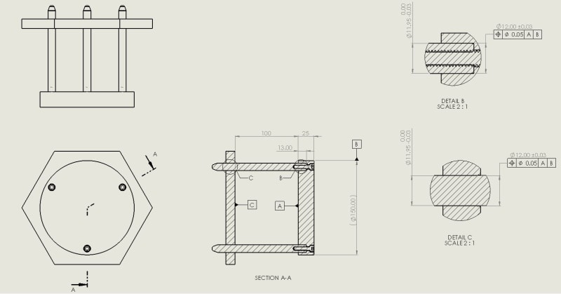
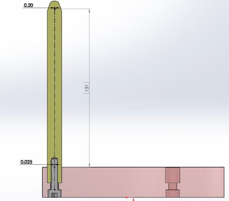
Here is a picture of a simplified drawing (forgive me it's far from being perfect) so you might better understand what sizes and precisions we are talking about:
2.2_zaqoyh.jpg


What really made me wonder how it actually works is the fact that the parts are manufactured separately and independently.
When I roughly calculated the optional deviation of the pin when we look at its tip I saw that a position of a hundredths mm may lead to a tenths mm deviation in the far side, where the guided upper plate is being interfaced, and theoretically it should stuck.
3_m07nxx.jpg


I would like to know what is the right design when we need a tight guiding.
it seems that if we manufacture the parts separately with realistic tolerances we have no chance to succeed.
 
Replies continue below

Recommended for you

1. The pins aren't perfectly rigid. They can, and will, deflect to accommodate slight deformation.
2. "Guidance" in which direction and resisting what directions of forces and torques? It will "guide" certain directions of motions and forces well, and others not well at all.
 
Looks like a 3-pin version of a normally 4 guide pin injection moulding tool. Guide pins, bushings etc are all available seperately so just buy them. Probably be much cheaper as well as having spares readily available.

Also the pins aren't located as sktch. Much better. Have a look at mould tool die set website. (e.g There are plenty of others)

Politicians like to panic, they need activity. It is their substitute for achievement.
 
Hey BrianPetersen,

The deflection matter was also one of my assumption, but I then thought to myself that a deflection may only help to insert the pins into the plate's holes with some force, but a guidance may become more problematic (involving greater forces) as long as we go down to the base plate.
As for your questions, the guidance is vertically towards the base plate, and no big force (this device is used by a worker and is operated manually) is exerted.
 
Hey Pud,
I looked at the link and found some interesting solutions (that can replace some of the self manufactured parts), like this one:

But as long as the entire kit (2 plates with mounted bushings and pins) isn't supplied the problem I presented earlier still exists, because the problem stems from the holes position in the plates and less as a result of the fit between the pin and the bushing.
 
If I clamp the top and bottom plates together and bore the holes on a jig grinder they will be nearly perfectly located and square.
We made 4 post dies and you could flip the top plate over or end for end and the fit was still within teh slide bearing clearance.

= = = = = = = = = = = = = = = = = = = =
P.E. Metallurgy, consulting work welcomed
 
Thanks EdStainless, but it means you have a constraint of mutual machining while I wrote all the parts are manufactured separately.
 
Regardless it will still require jig grind.
And will be precise holes and true position.
It works because it's small.
If it was match drilled and ground
It would work to.

Since there will be slight deflection
When assembled it will be precise.

So if it works why change it.
 
Assemble the parts loosely. Hold the upper plate in place against the lower plate. Then tighten the capscrews. All should then align.

Ted
 
Status
Not open for further replies.

Part and Inventory Search

Sponsor