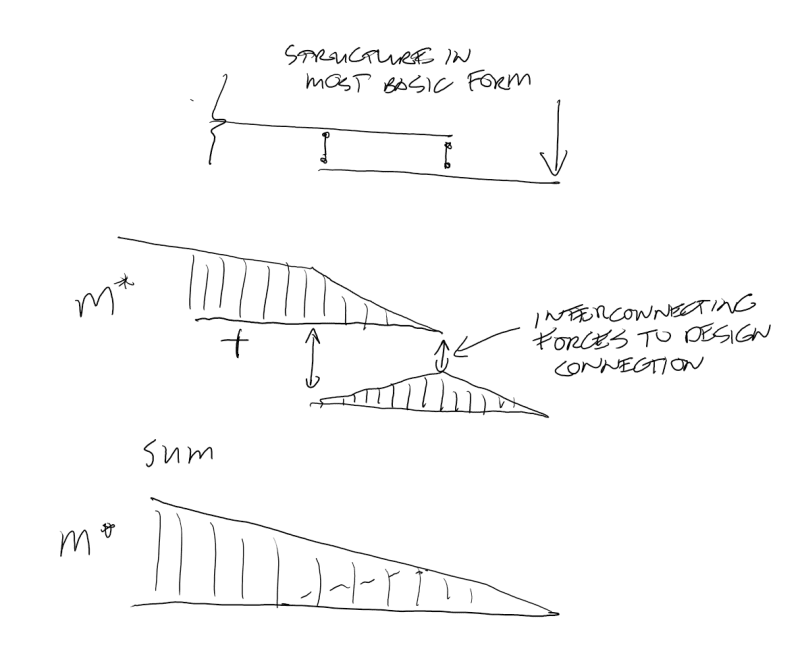
Hello, working on a pair of transport beams to move a large piece of equipment on a flat deck, beams will cantilever off the ends of the trailer to pick up the loads, think Two Unequal Concentrated Loads Unsymmetrically Placed as a load profile. Working to AS/NZ 3990 standard.
Got existing custom beams from a previous move but they are not stiff nor long enough. Increasing stiffness is straight forward enough, adding a plate to the bottom and RHS sections to the top. This also gets deflection down (Δ/l<250).
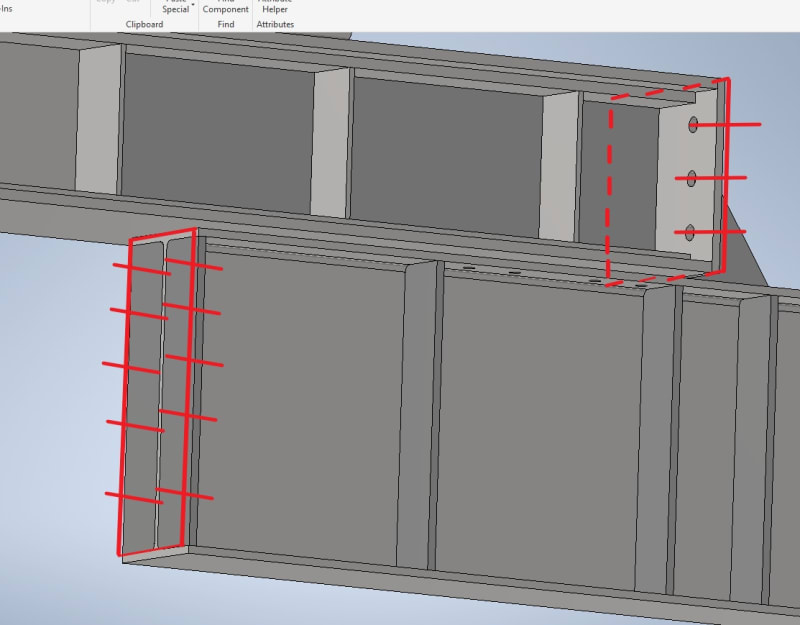
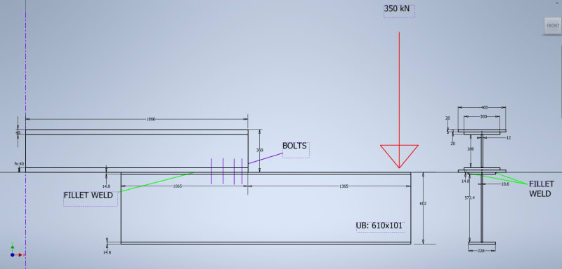
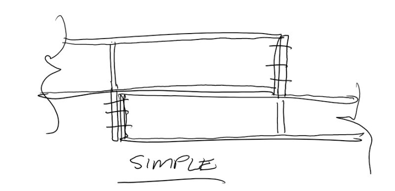
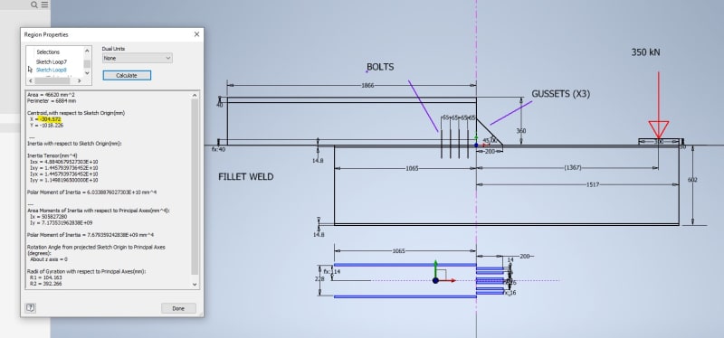
For length we'll add some UB I-Beams to the bottom of the existing (see below, UB's overhang vary on each end). The UB's top flange can weld to the existing, but thinking belt and suspenders, I will also add some bolts.
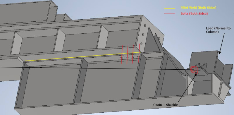
1. Given this load configuration, is it reasonable to assume both weld and bolts can take/share the load given bolts are preloaded? Or will it just be the weld until it fails then the bolts kick in? Not sure I can get weld strong enough on its own as flanges are only so thick.
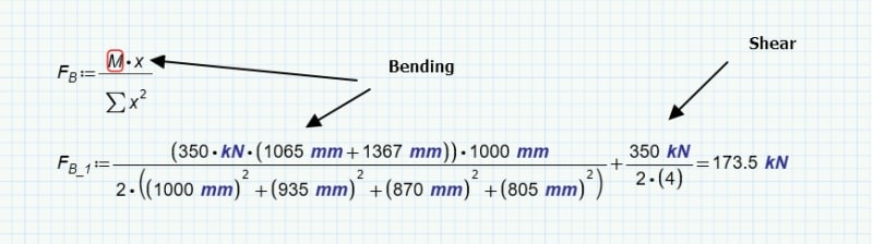
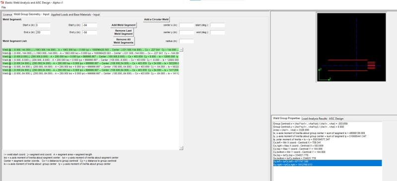
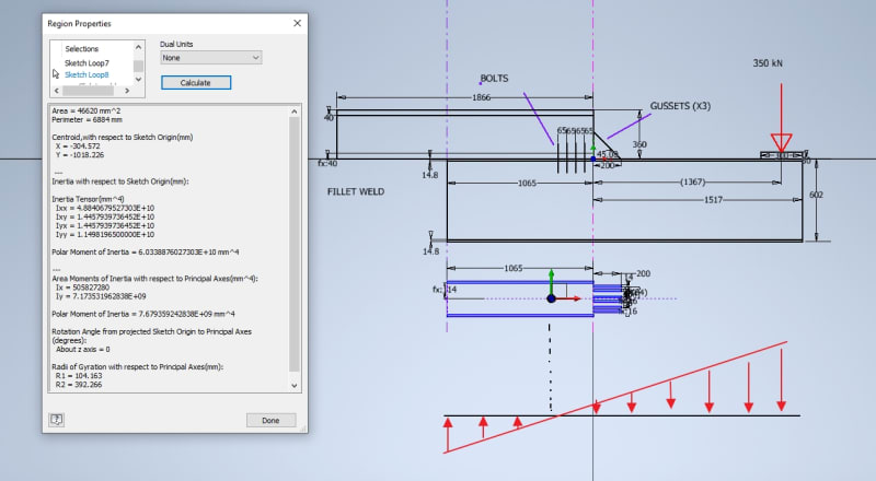
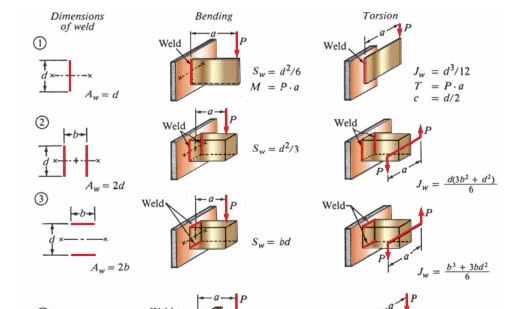
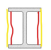
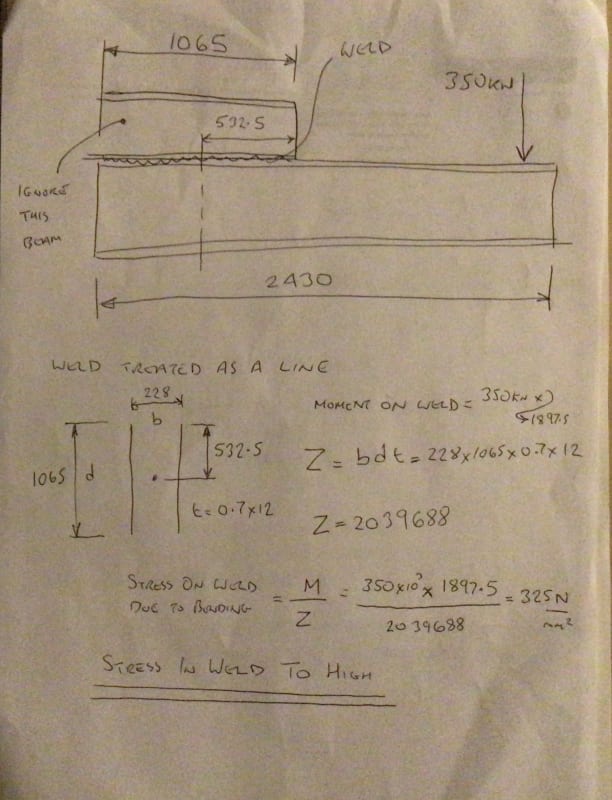
2. A reasonable way to evaluate the stresses in this weld? Currently evaluating as a line and have the below from my textbook in obtaining a "section modulus" for the weld (f=M/S_w [N/m]), but none are exact to how the load is in relation to the weld. Currently assuming #2 as it appears to be applying the bending along length of weld which is more similar than #3 which is about its leg (if that's right?).
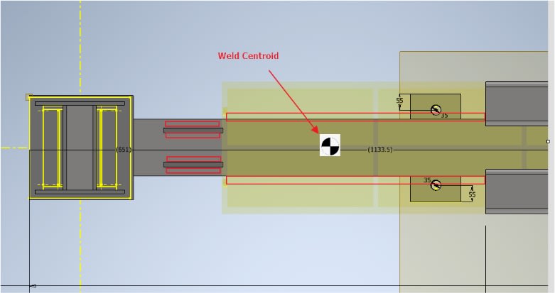
(Based on the assumption above) I found a weld centroidal position and calculated the moment on the weld (as a line) from this point to where the load is applied. Sounds reasonable? Okey
4. Torsional stiffness (from accelerating/deacceleration of load) is handled by 2 chains tied back to the flack deck. I believe this should be sufficient to combat lateral torsional buckling given strong enough chains? Or are stiffeners/other means better?
5. Bolt pattern is calculated by assuming the UB would pivot about the far end of the UB (worst case), confident in this but thought I'd check.
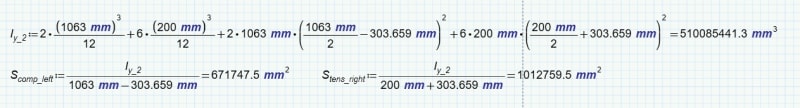
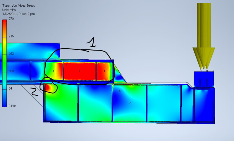
6. I checked the bending and shear stresses at various points across the beam (where beams stack, highest moment, about ends..etc) however the FEA in 2 sections are showing much higher stress than the hand calcs (bending and shear) and not sure why. Looking to add minimal amounts of plates, web doublers, stiffeners as required. From the calcs this should be a stronger section where the 2 beams double up...
Scale set to .9σy AS 3990. Bending is .6σy and .4σ_y for shear ((.6σy)2+3*(.4τy)2).5 = .9σy ?
Apologies if a bit much, any guidance, comments or suggestions is much appreciated. Left out number as much as possible as just looking at getting ideas on how to improve and I'll happily do the leg work in calcs.
Cheers,
Got existing custom beams from a previous move but they are not stiff nor long enough. Increasing stiffness is straight forward enough, adding a plate to the bottom and RHS sections to the top. This also gets deflection down (Δ/l<250).
For length we'll add some UB I-Beams to the bottom of the existing (see below, UB's overhang vary on each end). The UB's top flange can weld to the existing, but thinking belt and suspenders, I will also add some bolts.
1. Given this load configuration, is it reasonable to assume both weld and bolts can take/share the load given bolts are preloaded? Or will it just be the weld until it fails then the bolts kick in? Not sure I can get weld strong enough on its own as flanges are only so thick.
2. A reasonable way to evaluate the stresses in this weld? Currently evaluating as a line and have the below from my textbook in obtaining a "section modulus" for the weld (f=M/S_w [N/m]), but none are exact to how the load is in relation to the weld. Currently assuming #2 as it appears to be applying the bending along length of weld which is more similar than #3 which is about its leg (if that's right?).
(Based on the assumption above) I found a weld centroidal position and calculated the moment on the weld (as a line) from this point to where the load is applied. Sounds reasonable? Okey
4. Torsional stiffness (from accelerating/deacceleration of load) is handled by 2 chains tied back to the flack deck. I believe this should be sufficient to combat lateral torsional buckling given strong enough chains? Or are stiffeners/other means better?
5. Bolt pattern is calculated by assuming the UB would pivot about the far end of the UB (worst case), confident in this but thought I'd check.
6. I checked the bending and shear stresses at various points across the beam (where beams stack, highest moment, about ends..etc) however the FEA in 2 sections are showing much higher stress than the hand calcs (bending and shear) and not sure why. Looking to add minimal amounts of plates, web doublers, stiffeners as required. From the calcs this should be a stronger section where the 2 beams double up...
Scale set to .9σy AS 3990. Bending is .6σy and .4σ_y for shear ((.6σy)2+3*(.4τy)2).5 = .9σy ?
#1 In the web of the original beam where it overlaps the UB
#2 where the edge meets the bottom flat plate (even with a gap between end of UB and plate)
Apologies if a bit much, any guidance, comments or suggestions is much appreciated. Left out number as much as possible as just looking at getting ideas on how to improve and I'll happily do the leg work in calcs.
Cheers,
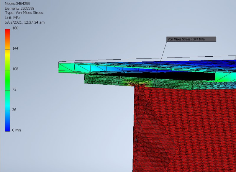
 1/3)*430 mPa = 143.3 mPa