Continue to Site

Eng-Tips is the largest engineering community on the Internet

Intelligent Work Forums for Engineering Professionals

  • Congratulations KootK on being selected by the Eng-Tips community for having the most helpful posts in the forums last week. Way to Go!

Cantilever Beam with Flange to Flange Bolt & Weld + FEA

Status
Not open for further replies.

tKc74

Mechanical
Jan 31, 2021
20
Hello, working on a pair of transport beams to move a large piece of equipment on a flat deck, beams will cantilever off the ends of the trailer to pick up the loads, think Two Unequal Concentrated Loads Unsymmetrically Placed as a load profile. Working to AS/NZ 3990 standard.

Got existing custom beams from a previous move but they are not stiff nor long enough. Increasing stiffness is straight forward enough, adding a plate to the bottom and RHS sections to the top. This also gets deflection down (Δ/l<250).

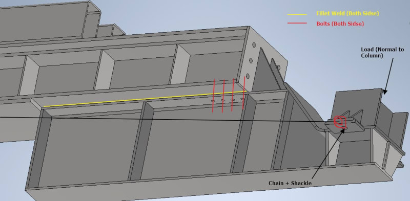
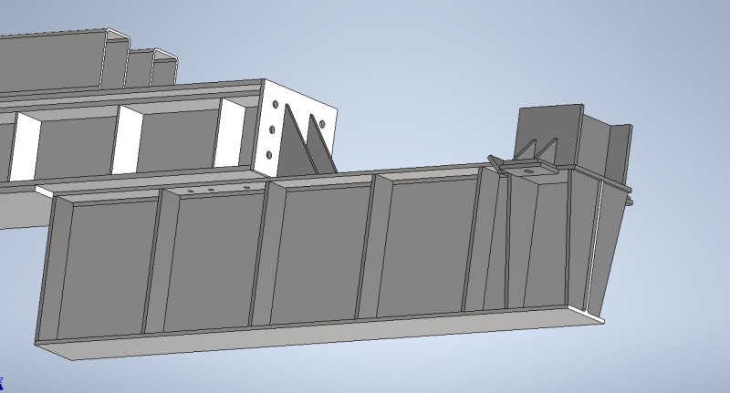
For length we'll add some UB I-Beams to the bottom of the existing (see below, UB's overhang vary on each end). The UB's top flange can weld to the existing, but thinking belt and suspenders, I will also add some bolts.
Beam_ehsacg.jpg
Beam_2_lyncjs.jpg


1. Given this load configuration, is it reasonable to assume both weld and bolts can take/share the load given bolts are preloaded? Or will it just be the weld until it fails then the bolts kick in? Not sure I can get weld strong enough on its own as flanges are only so thick.

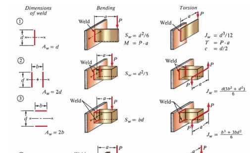
2. A reasonable way to evaluate the stresses in this weld? Currently evaluating as a line and have the below from my textbook in obtaining a "section modulus" for the weld (f=M/S_w [N/m]), but none are exact to how the load is in relation to the weld. Currently assuming #2 as it appears to be applying the bending along length of weld which is more similar than #3 which is about its leg (if that's right?).
Geometry_Factors_for_Weld_Analysis_V2.0_jrvyof.jpg


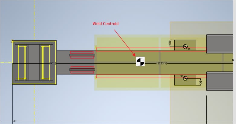
(Based on the assumption above) I found a weld centroidal position and calculated the moment on the weld (as a line) from this point to where the load is applied. Sounds reasonable? Okey
Weld_Centroid_zvdecx.jpg


4. Torsional stiffness (from accelerating/deacceleration of load) is handled by 2 chains tied back to the flack deck. I believe this should be sufficient to combat lateral torsional buckling given strong enough chains? Or are stiffeners/other means better?

5. Bolt pattern is calculated by assuming the UB would pivot about the far end of the UB (worst case), confident in this but thought I'd check.

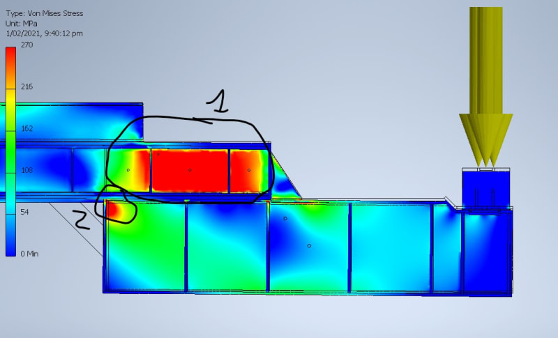
6. I checked the bending and shear stresses at various points across the beam (where beams stack, highest moment, about ends..etc) however the FEA in 2 sections are showing much higher stress than the hand calcs (bending and shear) and not sure why. Looking to add minimal amounts of plates, web doublers, stiffeners as required. From the calcs this should be a stronger section where the 2 beams double up...
Scale set to .9σ[sub]y[/sub] AS 3990. Bending is .6σ[sub]y[/sub] and .4σ[sub]_y[/sub] for shear ((.6σ[sub]y[/sub])[sup]2[/sup]+3*(.4τ[sub]y[/sub])[sup]2[/sup])[sup].5[/sup] = .9σ[sub]y[/sub] ?
#1 In the web of the original beam where it overlaps the UB​
#2 where the edge meets the bottom flat plate (even with a gap between end of UB and plate)​
FEA_kefk4w.jpg


Apologies if a bit much, any guidance, comments or suggestions is much appreciated. Left out number as much as possible as just looking at getting ideas on how to improve and I'll happily do the leg work in calcs.

Cheers,
 
Replies continue below

Recommended for you

Concentrating on the FEA output you have given in the beginning there are a few contradictions:
1. The upper beam web shows very high stress but the flanges show almost zero stress.
2. Stress in welded/bolted area is almost zero.

I suspect there could some modeling discrepancy which you should check.


Engineers, think what we have done to the environment !
 
On further checking with my FEA software with some simplification (omitting some details) it appears that the webs of the beams are indeed highly stressed. Explanation may be that these are not simple beams as lengths are small.
To be safe as someone suggested, it may be better to close the sides to make similar to box sections. This way the vertical plates parallel to webs will share load with the existing webs.

Engineers, think what we have done to the environment !
 
Hi tKc74

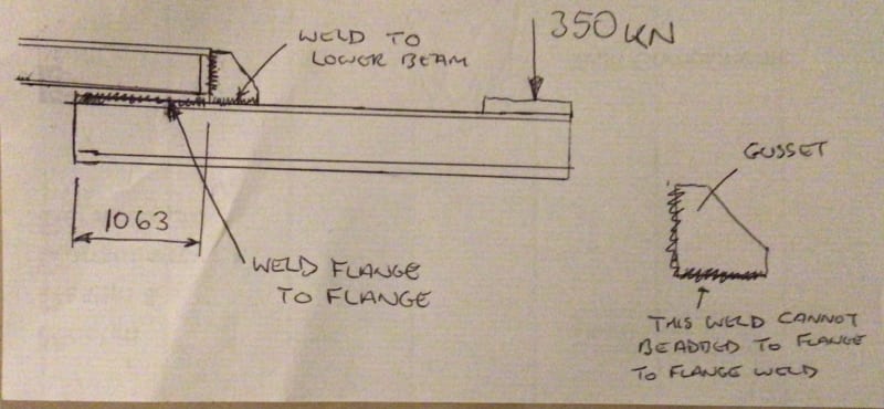
Okay I agree with the formula you found however I don’t think you cannot apply it to your situation in the way you have done, you have assumed the welds are continuous along both the flanges of the upper and lower beam but they are not.The weld running on top of the lower beam only connects both flanges for a length of 1063mm hand the additional 200mm of weld connects only the flange of the lower beam to a gusset, the gusset is then connected to the upper beam but by means of a vertical weld via a vertical end plate.So I don’t believe the welds between the lower flange and the gusset can be assumed work with the 1063mm long weld connecting both flanges together.
FB439EF8-0944-44BC-8496-DD176F95EC02_y97ob9.jpg


“Do not worry about your problems with mathematics, I assure you mine are far greater.” Albert Einstein
 
Hi,
goutam_freelance
Really appreciate the check up on the FEA, I will be adding vertical plates plates (12mm thick, both sides, 25mm away from the center of the flange) to share some of this load.

desertfox
The weld formula provided doesn't assume the weld is continuous (i.e one continuous weld) similar to the example from Hoberts P.19 (P.11 in PDF) under 9.3 Example 2, the welds can be discontinuous, which is the case I have. Are you able to give more detail as to why you believe this?

You're looking at it as if the gussets and the upper beam are different objects?
desertfox said:
The weld running on top of the lower beam only connects both flanges for a length of 1063mm hand the additional 200mm of weld connects only the flange of the lower beam to a gusset, the gusset is then connected to the upper beam but by means of a vertical weld via a vertical end plate

What I think the way to look at it is that the gussets are allowing for 6 (2 welds per gusset) additional 200mm in parallel welds that are to be added to the end of the 1063mm flange to flange weld. I don't see how this argument is flawed, but open to criticism.

There has to be some correct way to combined these gussets, its common practice to include gussets to increase weld strength, it would be overly conservative to completely ignore the gussets welds, when in reality the gussets welds would be taking up some of the stress in the welds, simply ignoring is not close to reality, not even by a conservative view point.

“If the women don't find you handsome, they should at least find you handy.” - Red Green
 
Hi tKc74
The welds may be discontinuous but they are all on the same plane in that paper you provided which is what I really meant when I said continuous,there was mention of 3D weld properties but I didn’t see anything similar to what we are looking for and I even did a internet search.
But if you look at the welds the 200mm welds at the gusset connect to the top beam with welds at 90 degrees to the 1063mm welds we are interested in, the centroid of the gusset welds will lie in a different position to the (flange to flange) weld and depending on where the neutral axis sits in the vertical position of the gussets I would expect the stiffness and stresses to be different than those in the flange to flange connection. Well ignoring the gusset welds might well be very conservative or even unrealistic however to me it would be safe, also the calculations you did originally ignore the vertical gusset weld which connects the the top beam via a plate to the lower beam but I cannot see how a welds at 90 degrees to welds we are interested in can act as one. I will do aearch later to see what I can find. Another point is the flange to flange weld just stops at the end of the 1063mm dimension which might become a stress raiser.


“Do not worry about your problems with mathematics, I assure you mine are far greater.” Albert Einstein
 
Hi desertfox, thanks again for all your comments and working thru this with me, much appreciated!

Okay I get what you mean by 3D, but the base of each weld lines on the same plane, that is the top flange of the lower beam. The welds all connect to the same object with their base on the same plane, their weld legs do go off in opposite directions.

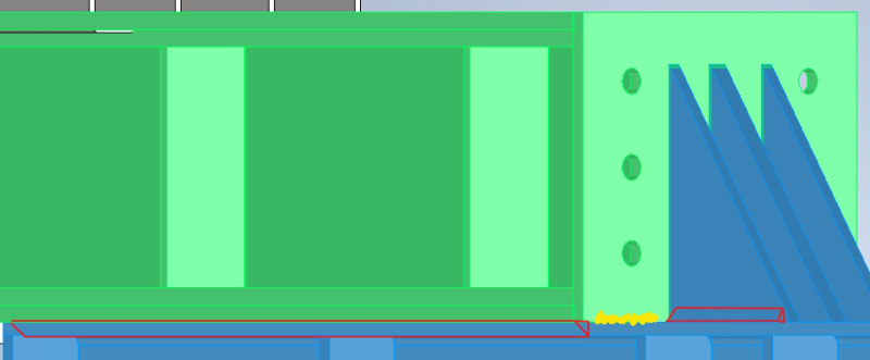
Might just be me, but not seeing a clear reason why these two (red fillets below) welds don't compliment each other as described above.
Welds_qcfzk3.jpg


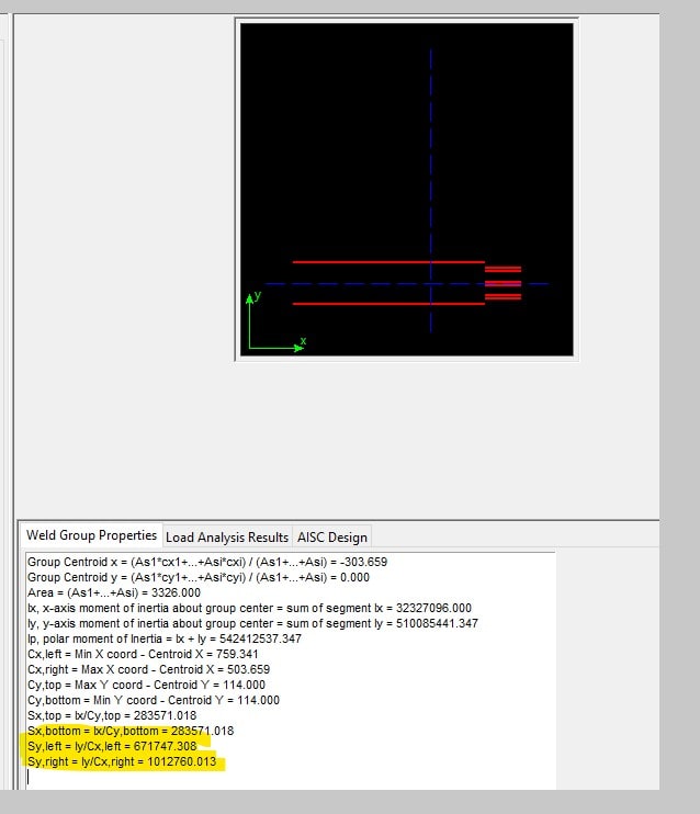
When I look at the weld centroid as per below, and the screen shot above, it just looks right that the centroid is there, and that the beam will want to rotate about this axis (blue vertical line below).
Screenshot_2021-02-09_000139_x8hgss.jpg


The ends will likely be filled in with the yellow scribble above, though they probably wont connect to the red welds I have shown as I've heard that connecting 3 welds together from different angles is a no-no structurally (weld stress concentration).

Thanks in advance.

“If the women don't find you handsome, they should at least find you handy.” - Red Green
 
Hi tKc74

You’re very welcome it’s an interesting problem you have👍.

The way I came to may conclusion was this, imagine the gussets are welded to the top flange of the lower beam as they are now, but were not welded to the vertical face at the end of the upper beam, now if this were the case the six 200mm long welds would not contribute anything to the welded upper and lower flange beams when the 350KN load is applied, now weld the gussets to the vertical plate of the upper beam and apply the 350KN load, the load path is transferred via the gussets to vertical end plate of the upper beam and and their welds but these welds are at 90 degrees to the original welds we were considering.
Is it possible that you could increase the lower beam in length on the underside of the upper beam to allow longer welds on the flange to flange connection? The over hang from left to right could remain the same as now and you would just extend the 1063mm overlap of the two beams in the right to left direction and thereby extend it sufficiently enough to allow the stress in the flange to flange connection to be below the allowable stress and then this problem goes away.


“Do not worry about your problems with mathematics, I assure you mine are far greater.” Albert Einstein
 
Apologies for the delayed reply.

1.) "Figured as much, I should design each to handle 100% load then?"
Yes I think so, and that seems to be what others in the thread are suggesting.​

2.) "How does the load path get more complicated with the gussets? I figured it was creating a smoother path for the load?"
With this I meant that some of the load will go into the flange to flange weld and some into the gussets, splitting the path in a way that makes the analysis more difficult. I think this caused some of the confusion with calculating the weld centroid in the thread. But by all means I think the gussets are a good idea for smoother load path overall. I would be warry of having too many as you've shown in some of the pics because of difficult weld access, but you can get around that.​

3.) "I've considered a box section. Can I add plate from outside edge to outside edge of the flange? Or is it better to be between the flanges?"
Yeah that's not a bad idea, as it's relatively easy to do and you'll get some bonus strength too. I'd suggest outside to outside to avoid tolerance difficulty with fitting them inside. I'm not sure that it matters too much here though.​

5. "I have used diagonal stiffeners and it doesn't make much of a difference."
It looked like high stress in the upper beam panel zone on the FEA picture and I think a diagonal could alleviate that, but I'm glad you explored them at some point. Also you couldn't use them and do the box beam thing at the same time.​

Anyway, good luck with this and keep us posted on what you end up with!
 
Status
Not open for further replies.

Part and Inventory Search

Sponsor