Continue to Site

Eng-Tips is the largest engineering community on the Internet

Intelligent Work Forums for Engineering Professionals

  • Congratulations KootK on being selected by the Eng-Tips community for having the most helpful posts in the forums last week. Way to Go!

Cantilever (fixed-free beam)with point load - shear deformation

Status
Not open for further replies.

Batzo

Civil/Environmental
Apr 21, 2020
46
Why for a cantilever (fixed-free beam) with a point load at the end,
the cross section rotations are equivalent between a Timoshenko and Euler Bernoulli Beam?
 
Replies continue below

Recommended for you

Mathematically speaking, I understand.
But physically speaking, I cant see why it is right
 
Batzo said:
But physically speaking, I cant see why it is right

If you draw elevations of the beam deflected shape for flexural and shear deflection it should become clear.

For flexural deflection the top and bottom surfaces change in length, and the vertical sections rotate.

For shear deflection the top and bottom surfaces remain the same length. The top and bottom surfaces have the same inclination, and the vertical sections remain vertical, so the rotation due to shear deflection is zero. It is the rotation of the vertical sections that is transferred to connected beams, so the shear deflection does not contribute to that rotation.

For sloping or vertical beams, substitute longitudinal and transverse for "top/bottom" and "vertical" respectively.


Doug Jenkins
Interactive Design Services
 
Dear Batzo,

Please note the Timoshenko's Beam Theory is the most rigorous mathematical model widely used to describe the lateral deformation of beams in the commercial FE packages.

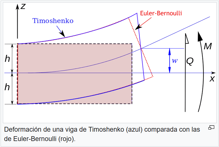
The beam theory according to Bernoulli-Euler, also known as the Classical beam theory, is a simplification of the Linear Theory of Elasticity to calculate deformations in beams. It applies to the case of small deformations in beams subject only to lateral loads. We could say that it is a special case of Timoshenko's Beam Theory.

teorias-de-vigas_jcb8or.png


Best regards,
Blas.

~~~~~~~~~~~~~~~~~~~~~~
Blas Molero Hidalgo
Ingeniero Industrial
Director

IBERISA
48004 BILBAO (SPAIN)
WEB: Blog de FEMAP & NX Nastran:
 
The only difference between Euler-Bernoulli and Timoshenko beam theory is that Timoshenko includes shear deflections. Both assume that axial loads do not affect transverse displacements, and ignore the displacement of the free end in the axial direction, so are only applicable to small deflections.

The diagram above is a bit misleading. If the intention is to show the deflected shape for an equal applied deflection at the right hand end, the Timoshenko curve should not be exactly horizontal at the left hand end, and the centre lines should only match at the two ends. Also Q and M will obviously be smaller for the Timoshenko curve than the Euler-Bernoulli.


Doug Jenkins
Interactive Design Services
 
Axial loads? Did u mean transverse loads?
I think I asked a simple question [surprise]
If this is the explanation for cantilever beam with point load at the end, so im fine and understood.

IDS said:
For flexural deflection the top and bottom surfaces change in length, and the vertical sections rotate.

For shear deflection the top and bottom surfaces remain the same length. The top and bottom surfaces have the same inclination, and the vertical sections remain vertical, so the rotation due to shear deflection is zero. It is the rotation of the vertical sections that is transferred to connected beams, so the shear deflection does not contribute to that rotation.
 
Batzo - my reference to axial loads was purely in response to the statement that "Timoshenko's Beam Theory is the most rigorous mathematical model widely used to describe the lateral deformation of beams in the commercial FE packages". The main point was that both theories are only applicable to small deflections.

My second sentence is referring to the diagram immediately above, which is a cantilever with a transverse point load at one end.

Did you try drawing some sketches of deflection shape due to flexural and shear deformation?

It would be instructive to draw a corrected version of the diagram posted by BlasMolero:
1. Assuming equal deflection at the right hand end.
2. Assuming equal transverse point load at the right hand end.
3. Assuming a point moment applied at the right hand end (so constant moment and zero shear).


Doug Jenkins
Interactive Design Services
 
Yes, I have tried.
That is why I wrote this post,
because I couldn't see it
 
Status
Not open for further replies.

Part and Inventory Search

Sponsor