Continue to Site

Eng-Tips is the largest engineering community on the Internet

Intelligent Work Forums for Engineering Professionals

  • Congratulations KootK on being selected by the Eng-Tips community for having the most helpful posts in the forums last week. Way to Go!

Cantilever Retaining Wall - Varying Stem Thickness - Bar Development & Splices 3

Status
Not open for further replies.

JoelTXCive

Civil/Environmental
Jul 24, 2016
921
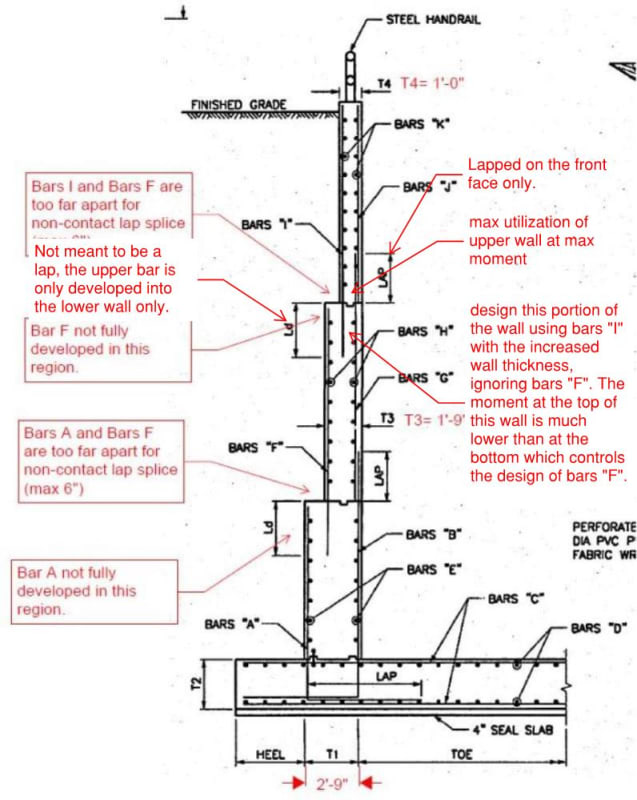
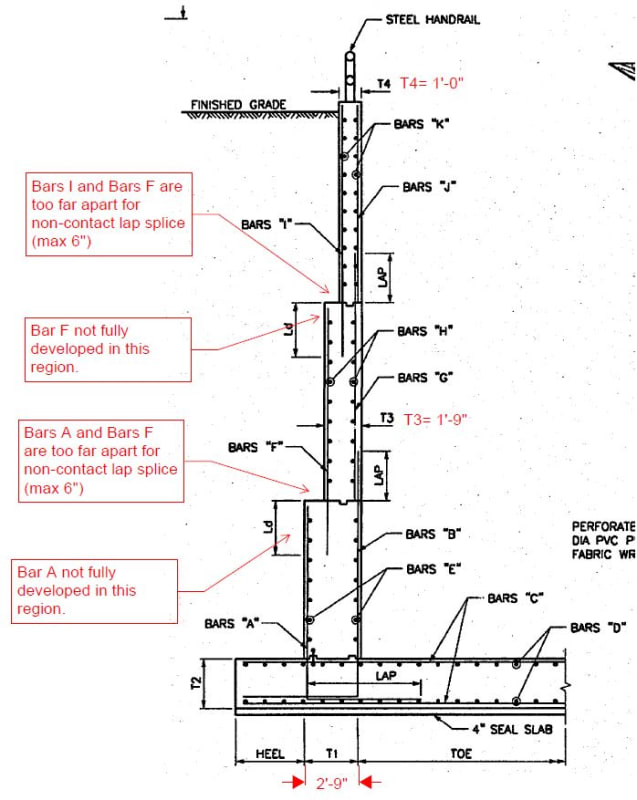
I'm designing some larger cantilever retaining walls that will have ~24ft of earth retained. I have an old 'go-by' project from 20 years ago and two things caught my eye (see below image). The wall below is a wing wall for a pump station headwall, and has a total height of 27' ft. The heel is small because overturning was not an issue due to other geometry.

Issue #1: Regardless of bar size, the lower bars at each segment end are not fully developed all the way to the top of the wall segment. You could do 180 hooks, or headed bars to improve the situation, but you still would not be fully developed all the way to the very tippy top of the wall segment, which would mean the moment capacity would be impaired there. Do you agree?

Issue #2: The bars between the segments are not lapped together. They are greater than 6" inches apart, which would be the maximum distance they could ever be apart if you wanted a non-contact lap splice. Maybe these bars do not need to be lapped though? If the lower bar was fully developed all the way to the end, and then the upper bar was embedded the full development length then this would be acceptable. The problem is, the lower is not fully developed (see issue 1 above).

What are your thoughts? And what could I do to improve?
canti_wall_question_it77nv.jpg
 
Replies continue below

Recommended for you

Cant't help with your bar questions, however, I would be concerned with overall sliding with such a small heel.
 
I did a 19 ft wall once. I talked to a contractor friend of mine and asked him about stepping the formwork to transition the stem from wide at the bottom to 12 inches at the top

He told me that it would be easier to simply slope the earth side formwork and tilt the associated rebar mat instead of tying up multiple mats.

I think that taller steel form systems make a tilted form easier than “old” methods of custom wood framed forms.

 
I am not an expert in solving situations like this, but I share your concerns. This whole thing may be moot based on what JAE has said, but for the sake of having a discussion purely on the bar development question, could the dimension Ld be chosen such that the upper bar is developed at the point where the lower bar loses development? In that way, the wall (in terms of math) would essentially change thickness at this point of bar development rather than at its physical change in thickness?
 
The typical detail I use in these situations is attached to this post. The rebar in the lower section of the wall is developed into the front face and the rebar from the upper section is considered as spliced with the bottom section rebar as the distance is only 4".

With a rebar distance of more than 6" I would have probably used a longer lap and additional stirrups to ensure the force transfer through a local strut and tie model.
 
 https://files.engineering.com/getfile.aspx?folder=a179c689-b425-4c9d-9eea-d483e1bf028e&file=Retaining_wall.jpg
When we've done larger walls like that, we've done as JAE suggests, with a tapered rear face. The detailing gets a little tricky if the height varies, but if you can step the height changes, it would be fairly straightforward.

We just got a value engineering proposal from Contech to substitute a precast panel system with mild reinforcing for the post-tensioned precast double T system I designed for one somewhat taller than yours. The panels would be embedded in a cast-in-place footing. Might be worth contacting one of their reps to see how it compares. I'm sure it would shorten the construction timeline.

Rod Smith, P.E., The artist formerly known as HotRod10
 
1) I think that you've identified a very real and very important concern with the offset laps.

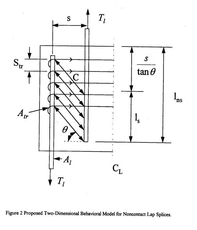
2) It is my strong belief that the 6" allowable offset does not apply in this case. I feel that it only applies in the plane of the concrete member where struts can be developed between bars and resisted internally.

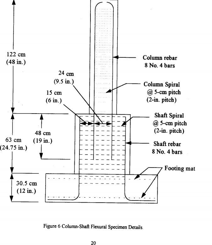
3) This has actually been tested and shown to be a real problem: Link

4) I would seek to avoid this condition wherever possible as others have stated.

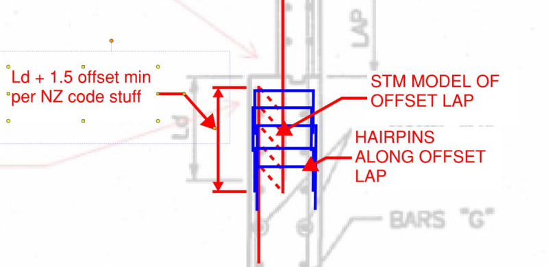
5) Were I to do this, I would do something similar to avscorreia but take it even further, as shown below.

c01_bsdyvz.jpg


c02_cfwb38.jpg


c03_bqm3mg.jpg
 
I agree that sloping a face is much better than stepping. But I prefer sloping the front face. That way, when the wall tilts or bends, it is still not beyond vertical, so doesn't attract speculation that it is going to fall over.
 
Interesting tidbit about battered walls. If the forms aren't anchored properly before the pour they will float up and spill the goods all over your jobsite.
 
I'm not sure there is any issues with the design shown above, when properly designed. The way I see this working is the thickness T3 portion of the wall is designed at the top of the T3 wall using Bars "G" and "I" only and ignors bars "F". Your moment at this location is much lower than at the bottom of T3 portion, therefore I would expect the increased thickness of the wall utilizing the reinforcing of "I" and G" would suffice. One thing I would recommend is that Ld should in this case be the development length of the larger bar, not the smaller, so that you can develop bar "F" (assuming "F" is larger than "I") at the top to provide proper bending resistance below where "I" ends. See below for some notes.
canti_wall_question_it77nv_ww8c7i.jpg
 
Aesur,

While I am sure there are a lot of retaining walls which have been done this way, it is wrong. Suggest you study KootK's post, and the paper he linked.
 
@hokie66, I am not sure you understand what I posted, if you were lapping the rebar then yes, you would need hairpins or something that develops the "F" bars, but what I propose is you are not lapping, you are designing the top portion of the T3 thickness wall using only the "I" and "J" bars with the increased thickness. The Ld distance then becomes the greater of that required for the "I" or "F" bars + clear distance. This allows the wall to be have bending resistance down to where you start using the "F" bars that are developed with a straight bar and no need for a hook. Are you trying to say that to develop the "I" bars you need to hook the "F" bars creating confinement? If so then I would ask how anything works because it's never done that way with anything when you develop a straight bar into a wall, foundation, beam, etc...
 
Aesur, if you had read KootK's posts on the subject, you would probably understand what hokie66 posted. I'll give you a preview - developed is not the same as anchored, and those bars need to be anchored in order for the wall to achieve the the design bending capacity.

Rod Smith, P.E., The artist formerly known as HotRod10
 
BridgeSmith, I apologize if I'm missing something, but I don't see anything in KootK's post about anchorage, it appears to be talking about non-contact lap splicing and secondary reinforcing. I'm pointing out that the image in the original post doesn't have a non contact lap splice. Please note that I haven't had a chance to read the 55 page document linked yet, but will when I get a chance.

But since you claim that developed bars are not the same as anchored let's discuss this.
Development length is the length of bar needed for the transfer of the stress from the steel to the concrete. Whether the concrete can take it or not is another issue which is where secondary reinforcing comes into play to deal with concrete breakout, etc. Anchorage length is the used when you don't have enough room to develop a straight bar, in this case you use a hook or bend in the reinforcing and can reduce the embed significantly. In this case as well secondary reinforcing should be considered if breakout of the concrete is an issue. By these definitions, anchorage and development are achieving the same thing, just with a different method due to constraints of what it's being developed into. Whether the wall in question needs this additional reinforcing is dependent on the forces.

Out of curiosity let's look at a concrete column attached to a concrete footing. The most common way of doing this is to hook the vertical column reinforcing into the foundation and rarely (in non-high seismic regions) does the footing have a top layer of reinforcing or other supplemental reinforcing (see the image below). In this case, why is it acceptable to have the vertical column reinforcing developed into the foundation, without "anchoring" it as you state?

detail23bprecastcol_vj50pb.jpg
 
Aesur said:
Whether the concrete can take it or not is another issue which is where secondary reinforcing comes into play to deal with concrete breakout, etc.

Actually, that is what I was referring to as anchorage. In the AASHTO Bridge Design spec, hooks are used as another way to provide development, and it is termed that way.

Adequate concrete strength to resist or transfer the tension from the non-lapped bar is the concern with the straight bar configuration shown for the stepped wall.

Btw, our bridge footings always do have a top layer of reinforcing. I suspect that providing anchorage for the vertical reinforcing is the reason the top layer is provided for footings exposed to seismic loading. It may not be critical to have full anchorage for footings not exposed to seismic loading.

Rod Smith, P.E., The artist formerly known as HotRod10
 
I will second JAE's comment. My experience with pump stations is to have tapered battered walls. Meaning sloping the backfill side of the wall (batter), this was confirmed by Peri formwork and a contractor as a preferred method, and varying the height of the wall along its length (tapper). For some walls, it can be advantageous to keep the wall thickness constant over the height.
 
Aesur said:
In this case, why is it acceptable to have the vertical column reinforcing developed into the foundation, without "anchoring" it as you state?

I don't believe that it is acceptable. Or, at the least, it is not acceptable without an investigation that goes deeper than just "developed". Consider:

1) If the tension present in the joint is flexural tension, then the appropriate detailing is as shown below.

2) For either flexural tension or direct tension, checks akin to punching shear are appropriate. A recent, detailed discussion of this can be found here: Link. That may be the thread BridgeSmith was thinking of when he referenced my previous work on similar issues. It's hard to tell though. I'm sort of the "Anchorage Maven" around these parts and there are numerous threads here where I've harped on that issue.

c01_apocxg.jpg
 
@KootK, Thank you for the input and I agree with you on this. When I design a footing for significant uplift or moment I tend to add the top reinforcing, I even take it a step further and depending on the size of my foundation compared to the development length needed for a straight bar I hook the top and bottom reinforcing at the ends to develop it. One way I look at it is, if I can show that Chapter D design works for breakout, etc. then the top reinforcing wouldn't be needed. I point this out because I have noticed that the "standard of care" in my area appears to be lacking and this is just one area I have noticed it. Things like this were why I and a few others formed our own company to change the standard of care.
 
@BridgeSmith, Thank you for the clarification. I am not very fluent in AASHTO terminology yet, but hope to be soon.
 
Aesur said:
Things like this were why I and a few others formed our own company to change the standard of care.

Ditto. I'd love to discuss that with you somehow/sometime.
 
Status
Not open for further replies.

Part and Inventory Search

Sponsor