Continue to Site

Eng-Tips is the largest engineering community on the Internet

Intelligent Work Forums for Engineering Professionals

  • Congratulations KootK on being selected by the Eng-Tips community for having the most helpful posts in the forums last week. Way to Go!

Cantilever Retaining Wall - Varying Stem Thickness - Bar Development & Splices 3

Status
Not open for further replies.

JoelTXCive

Civil/Environmental
Jul 24, 2016
921
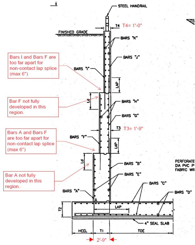
I'm designing some larger cantilever retaining walls that will have ~24ft of earth retained. I have an old 'go-by' project from 20 years ago and two things caught my eye (see below image). The wall below is a wing wall for a pump station headwall, and has a total height of 27' ft. The heel is small because overturning was not an issue due to other geometry.

Issue #1: Regardless of bar size, the lower bars at each segment end are not fully developed all the way to the top of the wall segment. You could do 180 hooks, or headed bars to improve the situation, but you still would not be fully developed all the way to the very tippy top of the wall segment, which would mean the moment capacity would be impaired there. Do you agree?

Issue #2: The bars between the segments are not lapped together. They are greater than 6" inches apart, which would be the maximum distance they could ever be apart if you wanted a non-contact lap splice. Maybe these bars do not need to be lapped though? If the lower bar was fully developed all the way to the end, and then the upper bar was embedded the full development length then this would be acceptable. The problem is, the lower is not fully developed (see issue 1 above).

What are your thoughts? And what could I do to improve?
canti_wall_question_it77nv.jpg
 
Replies continue below

Recommended for you

So... back to your ideas about the original detailing being adequate if designed correctly. I'd like to critique your proposal but, first, I need to understand it. Presently, I'm not sure that I do. It's always difficult to clearly express these kind of concepts with prose alone.

As I see it, things work like this with there being two, mostly binary choices:

1) You can use reinforced concrete theory to transfer the moments from the upper wall segments to the lower. This encompasses most of the suggestions and STM models suggested in this thread. Or;

2) You can use anchorage theory to transfer the moments from the upper segments to the lower. This basically amounts to appendix D / concrete in tension stuff.

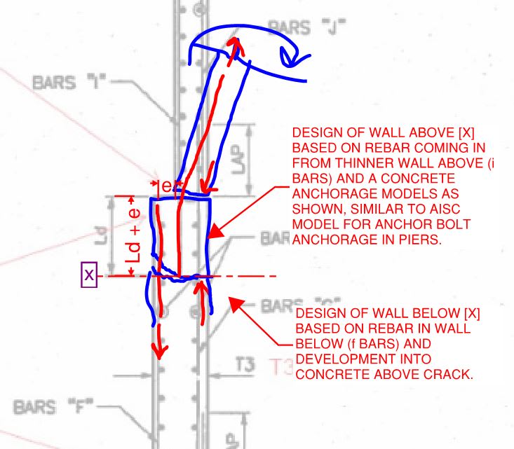
If I understand your solution correctly, it is #2 above and would reflect the model shown below. Is that correct?

I will always prefer path #1 to path #2 purely on the basis of perceived reliability. RC principles trump anchorage principles always and forever with respect to reliability as far as I'm concerned. But, then, that's just my personal preference and not a code requirement etc. So I'm happy to weigh the merits of your proposal once I've got a solid grasp on it.

c01_xgokk3.jpg
 
I'm trying to understand this a bit better:
KootK's Sketch said:
"...and a concrete anchorage model as shown similar to AISC model for anchor bolt anchorage in piers

What if you extended i bars Ld_i below "X". Meaning the total embedment for 'i' bars is Ld_i + Ld_f. Do you need to consider the AISC model?

If yes, what in ACI tells you this? Or says you are violating development rules?

One step further - Let's say T3 is massively thick so there is no reinforcment. Could you just embed the 'i' bars Ldh_i into the stem?

I guess I'm searching for the line between developed rebar and anchorage and how that is explained in ACI.


EIT
 
Thank you, everyone, for this very useful discussion. Before I started reading I was in the "looks fine to me!" camp, but now I'm seeing it the other way.

If you would be willing to indulge me, I'll outline my thought progression and see if it follows the prevailing line of thinking:

I initially thought that, because the bar was "developed" into the top of the next segment of wall, it would be fine. After all, the lower segment is designed for the moment at its base, so there's probably a lot more reinforcing in the lower section at a transition that you really need (the section above is designed for the same moment, but is half as thick with, I would think, less rebar). But after reading the paper KootK posted (skimming, if we're being honest) and trying to really get at the fundamental difference between anchorage and development, I realized my flaw. My load path was incomplete. below the point where the bar is fully developed, the load has to keep going somewhere - either by lapping with other reinforcement or (yikes) through the tensile strength of the concrete section. As it's embedded below the neutral axis, we'll can assume there will be flexural cracking and little to now actual tensile strength left. So I'm no longer too excited about the "develop it and forget it" approach. Sound about right?

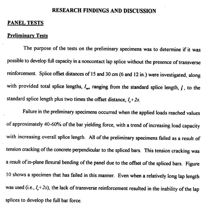
ACI 318-14 still has the same provisions for non-compact lap splices as those referenced in this 22 year old research paper, with no direction that I can see regarding transverse reinforcement. (Except development of headed reinforcement - the commentary there mentions transverse to create strut and tie.) You'd think they'd update that...

 
Never mind - KootK typed and sent his last message while I was doing mine essentially confirming what I was thinking.

Thanks again!
 
It seems that this thread has grabbed a few people by their imaginations. Fun. For those interested in the detailing principles being discussed here, the following are "must-considers" in my opinion:

1) This thread: Link. Here on Eng-Tips, it was that, wildly contested thread that got the ball rolling with respect to the difference between development and anchorage. The answers to a lot of people's questions can be found there.

2) With respect to OP's condition in particular, this discussion would be incomplete without giving consideration to the analogous condition with stepped masonry walls. You know the the drill:

- 12" on the bottom with bars centered.
- 8" on the top with bars centered.
- Offset lap and little to no opportunity for the clever detailing improvements proposed here.
- Gawd-awful, real world detailing fail that's surely out there right now threatening lives.
 
I'm liking this thread too! I'm still working on my design and actively monitoring.
 
RFreund said:
Do you need to consider the AISC model?

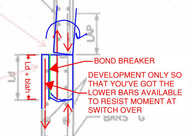
Firstly, let's be clear: I have not suggested that anyone use the AISC model. In the post where I mentioned that model, I was trying to envision what Aesur's been describing and the AISC model seemed quite similar to me. That was a guess at what Aesur might be thinking, not a recommendation from me. Now that I look at it, however, I see that my sketch conflates two separate ideas however. I see Aesur's proposal as either:

1) A purely anchorage solution wherein the presence of the [F-bars] is immaterial to that part of the connection or;

2) Truly the AISC model which I would consider to be a poor-man's / half-assed lap splice.

For #1, I'd like to replace my previous sketch with the one shown below. It's fictionalized but a much better representation of the concept.

RFreund said:
What if you extended i bars Ld_i below "X". Meaning the total embedment for 'i' bars is Ld_i + Ld_f.

No matter how long you make an offset lap splice, it's still an offset lap splice, right? Some thoughts on that:

3) Intuitively, one would think that, at some length of offset lap splice, you'd be okay.

4) Just because you lap from Denver to Cleveland, that doesn't mean that observers in the Cleveland suburbs will be seeing any bar tension in the off-loading bar. Elastic theory makes it clear that most of the lapping action takes place early on in the lap. This runs counter to #3 and one can envision a progressive unzipping of the lap regardless of how long it is.

RFreund said:
One step further - Let's say T3 is massively thick so there is no reinforcment. Could you just embed the 'i' bars Ldh_i into the stem?

Maybe, if:

1) The bars are small enough and;
2) The bar spacing is large enough and;
3) The concrete edge distances are generous enough.

Again, this is your thread for that: [link ][/url]

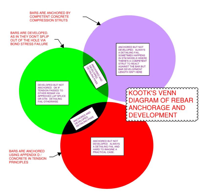
I like to think of this mathematically as shown below. Perhaps other will find that helpful.

RFreund said:
If yes, what in ACI tells you this? Or says you are violating development rules?

RFreund said:
I guess I'm searching for the line between developed rebar and anchorage and how that is explained in ACI.

To my knowledge, ACI does not say anything about this. Nor do most textbooks. Ideally, I'd like to see an ACI clause something like this:

1.0 This document is primarily concerned with reinforced concrete design which requires that all rebar tensions be anchored by concrete struts or approved lap splices to adjacent rebar. If you're doing something else, that's not reinforced concrete design. See chapter whaterver for voodoo anchorage procedures utilizing concrete in tension.

My guess is that ACI doesn't say this because they take it as being so fundamental and obvious that it doesn't actually need to be said. Clearly, they would be wrong about that as it causes endless confusion among concrete designers (me included back around the turn of millennium).

c01_gevagp.jpg

c02_jmsvfk.jpg
 
I recall an historical concrete failure that is documented in one of ACI's discontinued publications. The failure involved bent concrete frames where the concrete split between offset discontinuous longitudinal rebars.

In the past, for high tension loads, I have used the anchoring to concrete section of ACI (D for 318-11) for justifying embedment into the top of drilled piers where the rebar was fully developed on both sides of the expected concrete failure plane (the 1 to 1 1/2 slope).

For this situation either add hairpins with extended embedments or slope the backface rebar to eliminate the offsets (preferred).
 
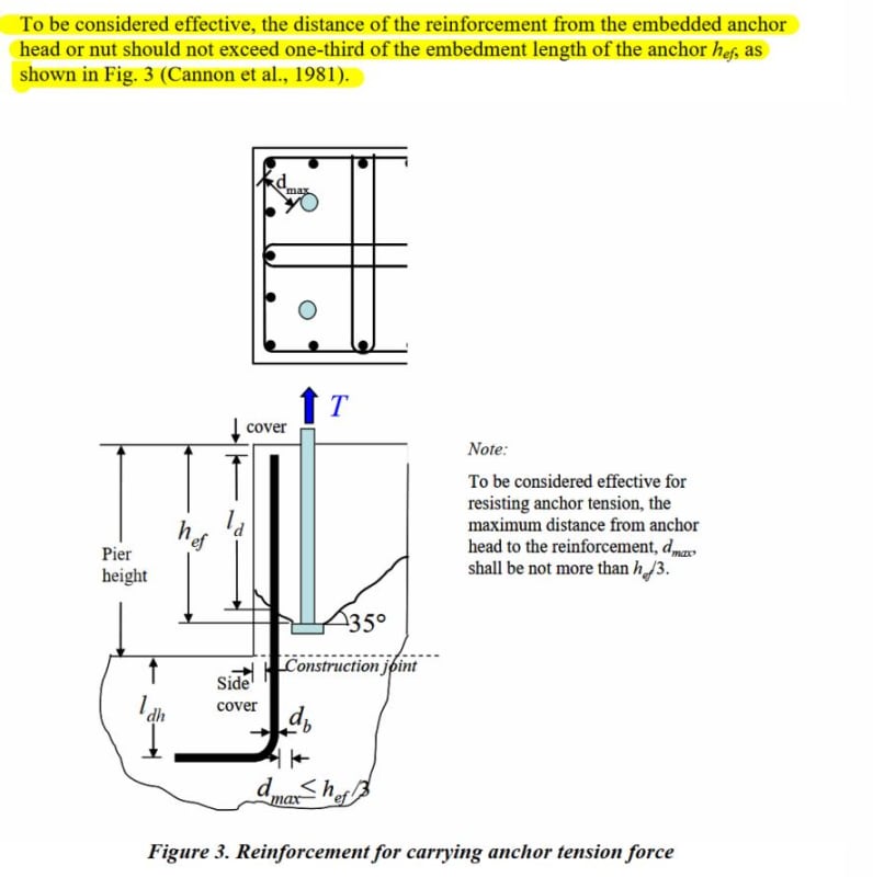
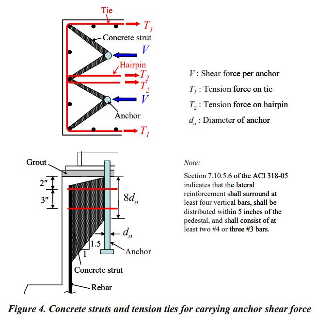
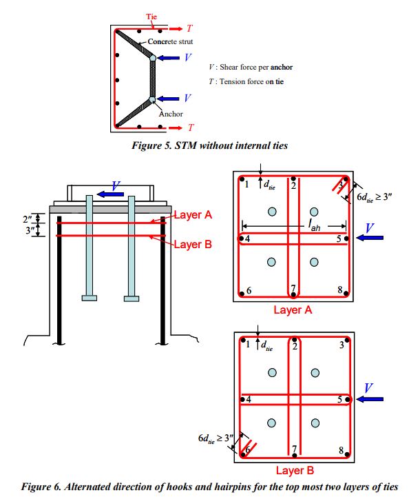
Here's a figure from a very famous anchor reinforcement paper. I believe this is applicable to our current situation and I would be inclined not to provide hairpins as long as these requirements are met:

conc_breakout_iarxlw.jpg
 
bhiggins said:
I believe this is applicable to our current situation and I would be inclined not to provide hairpins as long as these requirements are met:

The procedures in that document also require ties which function similarly to the hairpins in the retaining wall. The document treats the ties from a shear transfer perspective but, regardless, they're assumed to be in play. I'm not sure that Widanto meant for his tension solution to apply in the absence of the ties. That said, I believe that he does count on untied bars in the tension calcs.

Interestingly, as asides:

1) This is the AISC model that I mentioned, applied to concrete, pretty much verbatim.

2) Widanto's actually remiss in suggesting that Ldh is sufficient into the footing without additional checks.

c01_c614el.jpg


c02_buddas.jpg
 
I will say, however, that even in the absence of ties or hairpins, I like the situation a lot better with the upper bars un-deformed and terminating in a headed anchorage.
 
Could you argue that all of the shear will be transferred through the keyway, thus if the concrete wall is sufficient in shear it should be able to resist the strut forces? There is also a jump in the concrete thickness which will provide a very large surplus in shear resistance.
 
Oh, I'm not the least bit worried about the shear capacity. In that respect, I'd be happy with the original detailing, even without the keyways. I was trying to make the point that, in the Widianto stuff, the ties that are placed for shear resistance will also help to serve as cross ties for any offset spliced tension steel.
 
I've gotta say that I've also walked over to the Koot camp. I'll take a stab at it.

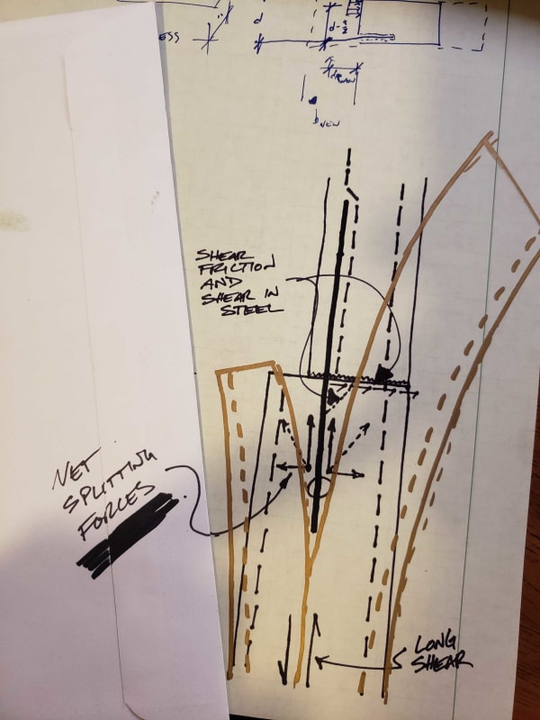
The failure that keeps coming into my head is the wall effectively 'splitting' in half where the 'i' bars develop into the middle stem. Think of the forces in the wall at that interface. You've got a bunch of horizontal (earth) shear pulling the outside face away from the backfilled face, via shear friction and shear in the bars. Youve got tension in your 'i' bars. Tension in the 'i' bars induces a splitting force into the section between bars 'f' and 'g', resisted by tension between the two 'lamella', composed of the rebar mats+half the wall thickness of concrete. Think of the - probably negligible - longitudinal shear between the front and back face of the wall (shearflow between compression and tension side). I think that was partially discussed in the other development length threads. Without some sort of tie, I'm buying into the 'i' bars splitting the top of the middle stem in half, reducing bond strength to zero.

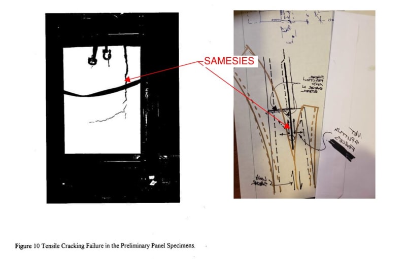
What I imagine is similar to Koot's bond breaker example, but the split occurring at the 'i' bar. See my crude sketch below. Exaggerated perhaps, but a plausible result, no?

The 2015 'infinite slab' development thread was frustrating. One way to think about it, which Koot alluded to in a way, imagine a bar embedded in an immovable, small diameter, concrete-fully-bonded-to-pipe pipe, say...4" in diameter - ignore the size, could be 2bar diam for sake of discussion. It is a matter of bond strength (perhaps could also be described as "pullout strength", wherein the bar must crunch its way through the paste between the bar deformations). Forget breakout, side face, or any other App. D type failure mechanisms other than the concept of bond/pullout. Development length effectively describes "how many deformations along the bar, reacting on the concrete local to each deformation, are required to resist the force required to yield the bar". Obviously 'number of deformations' is expressed as inches. Is anyone following me on that?

Designer's responsibility to properly anchor the developed bar. I.e., ensure a load path exists between the the developed bar and the foundation.

This thread is what I come here for.
20191016_222352_hysvjw.jpg
 
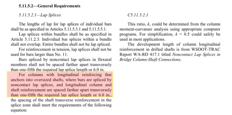
I was looking for something else in the AASHTO spec. this morning, when I ran across something that may be related to this subject. Section 5.10.8.4.2a has provisions for lap splices, non-contact lap splices, and requirements for longitudinal columns reinforcement that "anchors into oversized [drilled] shafts".

For non-contact lap splices, the distance between bars cannot exceed 1/5 of the lap splice length or 6".

For column steel in oversized drilled shafts (exceeding the 1/5 lap or 6") it has a fairly involved equation to calculate the required transverse reinforcement around the perimeter of the drilled shaft in the splice zone.

The commentary includes this statement:

The development length of column longitudinal reinforcement in drilled shafts is from WSDOT-TRAC Report WA-RD 417.1 titled Noncontact Lap Splices in Bridge Column-Shaft Connections. Eq. 5.10.8.4.2a-1 is based upon a strut-and-tie analogy of the noncontact splice with an assumed strut angle of 45 degrees.

Rod Smith, P.E., The artist formerly known as HotRod10
 
dold said:
See my crude sketch below. Exaggerated perhaps, but a plausible result, no?

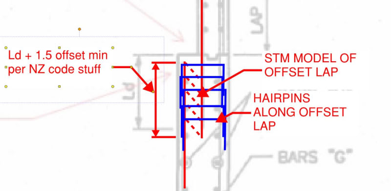
I almost posted the very same sketch when I was trying to describe the unzipping phenomenon on very long laps. The plausibility of it really is the issue in my mind. The function performed by the hairpins in the sketch below could also, plausibly, be performed by the concrete acting in through thickness tension. I've investigated this a bit numerically in the past with Mohr's circle combination with shear and flexural tension stresses. Numerically, it's not terrible and I suspect that this mechanism is what makes the poorly detailed version work out in the wild. That, and BS soil loads. A tricky part of that analysis is estimating how much wall length can be engaged this way for each bar. Most to all of the wall length I suspect.

I see this as a research gap as much as anything. The badly detailed connection surely has some capacity; somebody just needs to bring it into the lab and find out what it is and how to work it so that reliability is on par with reinforced concrete principles.

I've always found it strange that, when the industry started really looking into free anchorage design principals, we didn't start with rebar. Rather, we started with bolts etc and gradually got around to post installed rebar. I suppose that most of the research bucks probably came from Hilti etc.

dold said:
Obviously 'number of deformations' is expressed as inches. Is anyone following me on that?

I follow. In the world of precast, we often use connections comprised of a rebar dowel in a grouted, corrugated tube. This is very similar to the mental experiment that you've proposed I think. Pure bar development in the grout, corrugated tube anchorage in the surrounding concrete.

Also, a small digression: I vaguely remember you posting screen shots of a kick-ass snow drift spreadsheet some place on here. Is my recollection correct? Would you be be able to direct me to that thread? I'm looking to do something similar and hoping to use your stuff for inspiration

c01_iuancq.jpg
 
Very late to the party, but some thoughts on the original go-by design:

1) I don't like breaking up the tension rebar. I would personally like to keep it in the same plane.

2) With that, can your exposed face be tapered, or does it have to be vertical? That would solve a whole host of issues with the rebar detailing, though it would put a not-so-fun formwork situation onto your contractor.
 
Based on the Washington State DOT paper linked by KootK above, it seems safe to design with:

non-contact lap length = ld + e or ld + e + [top cover] when measured from the top of wall (e is the offset distance between longitudinal bars). Per code, ld shall be the larger of the development lengths for different bar diameters.


shear reinforcement must be provided at a spacing s = Av Fyv / (As Fy) x (ld + e) over the full development length and must be developed into the compression flange. This assumes compression struts form at a 45 degree slope and the shear confining reinforcement is equivalent in strength to the tension reinforcement being developed. Simply providing a longer development length without shear rebar would run the risk of initiating a crack between vertical bars when they first go into yielding followed by that crack propagating/unzipping as the yielding continues until premature failure


Some further avenues of research would look to answer:
- As the offset distance closes, can the compression strut angle be increased? It seems to me that a contact splice works because this angle goes to vertical.


- For slabs, can the shear confining reinforcement be replaced with a top hook from the bottom discontinued bar? The DOT study noted in their testing that distributing all of the shear confining reinforcement at the top exhibited premature failure of the tension bars due to splitting of the test beams and longitudinal bar pull out. I would think that for a significantly wide beam/slab, this splitting might not occur.


- Are there advantages when the lower rebar is larger than the upper rebar? Since the upper bar will only develop a shorter distance of the lower bar it seems that the compression strut angle would have to be greater than 45 degrees and thus require less shear rebar.
 
After reading BridgeSmith's latest, I decided to dig a little deeper on the whole, allowable 6" offset thing. Here's what I've got, tabled for consideration.

1) As I mentioned above, I've always considered the 6" option to apply only where the offset is in the plane of the member (wall, slab, etc). I've considered it to be not applicable where the offset is out of the the plane of the member. To my knowledge, ACI says nothing about this which kind of implies no limitation in this regard.

2) If OP's original sketch were detailed with 6" offset, this would mean that condition would be acceptable. I think that's nuts.

3) The AASHTO provisions that BridgeSmith cited are shown below. Based on the context, it's hard to see how that doesn't imply that 6" offsets out of plane are acceptable.

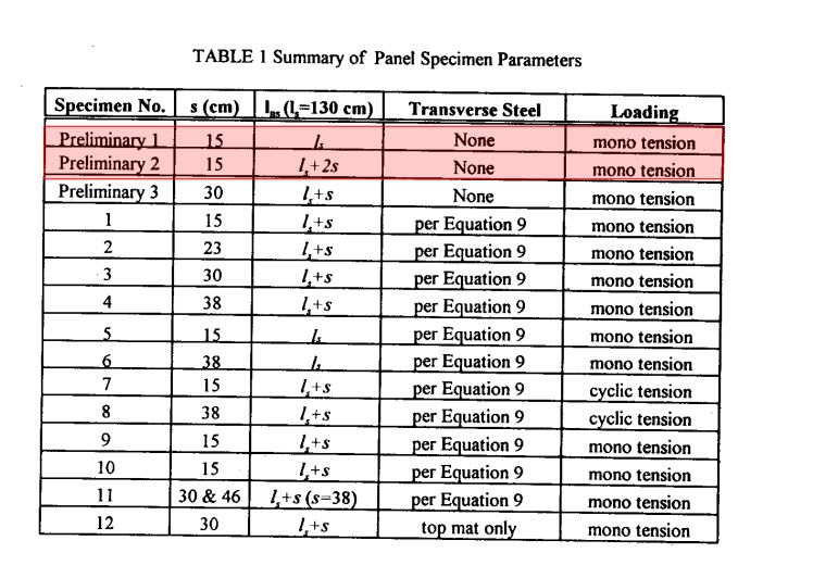
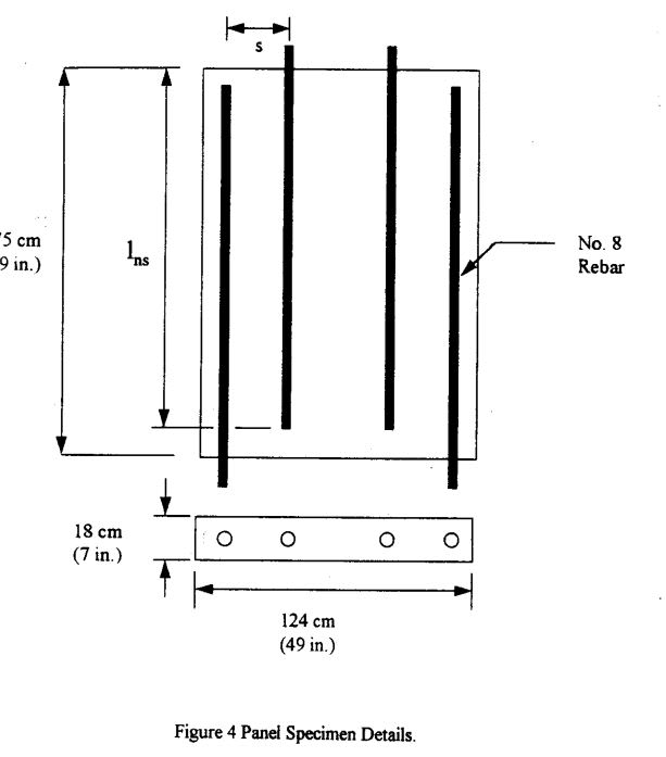
4) The DOT study tested 6" offests without transverse reinforcing and found that they failed pretty much in line with the sketch that dold worked up. And at as little as 40% of the yield strength of the bars. #8 @ 7" is a little dense but still.

5) The DOT study mentions the allowable 6" offset but then says nothing about the fact that their own testing of the condition would suggest that it would be an unsuitable provision for out of plane offset scenarios. Their wrap-up recommendation is to have transverse reinforcement for all offset splices but, given the ramifications of this, you'd think that they's specifically say something to the tune of: for the love of all that is wholly, do not to the 6" offset thing out of plane without transverse bars!

What gives?

c05_ahi3qf.jpg


c01_kyqsq1.jpg


c02_ua4cwe.jpg


c03_lvtydg.jpg


c04_jit2pv.jpg
 
Status
Not open for further replies.

Part and Inventory Search

Sponsor