Continue to Site

Eng-Tips is the largest engineering community on the Internet

Intelligent Work Forums for Engineering Professionals

  • Congratulations KootK on being selected by the Eng-Tips community for having the most helpful posts in the forums last week. Way to Go!

Cantilever Retaining Wall - Varying Stem Thickness - Bar Development & Splices 3

Status
Not open for further replies.

JoelTXCive

Civil/Environmental
Jul 24, 2016
921
I'm designing some larger cantilever retaining walls that will have ~24ft of earth retained. I have an old 'go-by' project from 20 years ago and two things caught my eye (see below image). The wall below is a wing wall for a pump station headwall, and has a total height of 27' ft. The heel is small because overturning was not an issue due to other geometry.

Issue #1: Regardless of bar size, the lower bars at each segment end are not fully developed all the way to the top of the wall segment. You could do 180 hooks, or headed bars to improve the situation, but you still would not be fully developed all the way to the very tippy top of the wall segment, which would mean the moment capacity would be impaired there. Do you agree?

Issue #2: The bars between the segments are not lapped together. They are greater than 6" inches apart, which would be the maximum distance they could ever be apart if you wanted a non-contact lap splice. Maybe these bars do not need to be lapped though? If the lower bar was fully developed all the way to the end, and then the upper bar was embedded the full development length then this would be acceptable. The problem is, the lower is not fully developed (see issue 1 above).

What are your thoughts? And what could I do to improve?
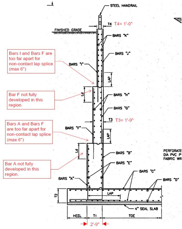
canti_wall_question_it77nv.jpg
 
Replies continue below

Recommended for you

I have not read all the responses. But if you design it and pretend the thicker wall of the LD portion was not there, I think that's fine? So on the design for the thickest part, it is only that thick up to H minus Ld.

 
DenverStruct said:
I have not read all the responses.

I'd read them. You're concept has been proposed and critiqued.
 
Kootk, I just read all of the responses, and I will be honest I am not following most of the responses (I am pretty green). So let me go back to basic and I could very well be very wrong.

So what really is development length then? Isn't lap splice length a function of development length? The reason lap splice is larger than development length is because the rebars do not have as much bonding with the concrete because it is so close to the other rebar? So if you draw 35 degree angle and the other rebar still have development length, it should be good?
 
DS said:
So let me go back to basic and I could very well be very wrong.

No worries. I'm glad to have you join the discussion.

DS said:
So what really is development length then?

Sorta depends who you ask but, if you're asking me:

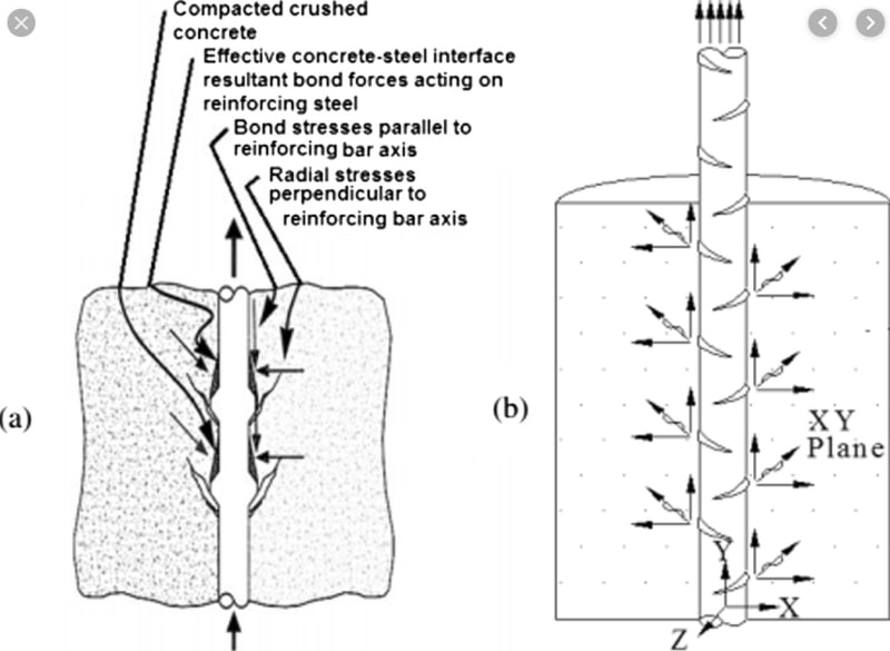
Development length IS the length of embedment that would produce bond stresses around the bar low enough that the bar would not be ripped right out of it's little, undamaged orifice.

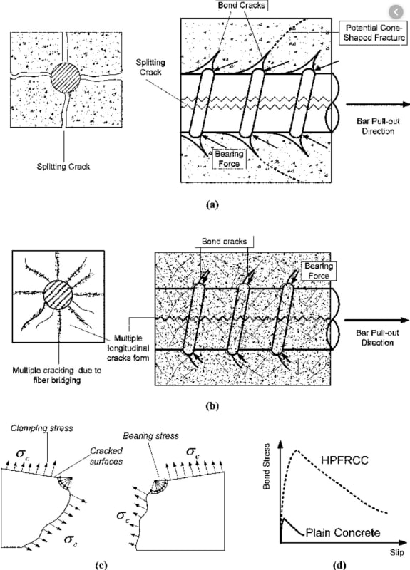
Development length IS the length of embedment that would prevent radial splitting around the bar at code limited amounts of cover.

Development length, on it's own, IS NOT a guarantee that your bar won't rip out from the concrete mass, taking some concrete with it.

DS said:
Isn't lap splice length a function of development length?

It is, mathematically and logically.

DS said:
The reason lap splice is larger than development length is because the rebars do not have as much bonding with the concrete because it is so close to the other rebar?

That is also my understanding. Once upon a time, it contact splices were actually prohibited by the code for just this reason. Of course that was eventually deemed to be... ridiculous.

DS said:
So if you draw 35 degree angle and the other rebar still have development length, it should be good?

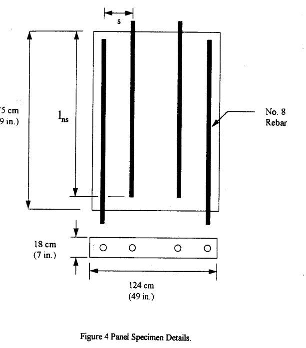
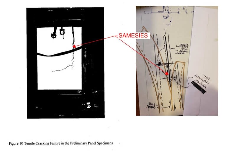
Somewhere on the continuum between "Hell no" and "Maybe kinda", again depending on who you ask. The details of this are spread out throughout this thread and it's not practical for me to regurgitate them all here. Maybe give it another scan and ask specific questions where you have them. The testing shown below is basically the situation that you've described. And you can see how well that worked out.

c01_mjwoyb.jpg


c02_ekbuxq.jpg
 
Well yeah, that was the point. If the panel were transversely reinforced, they would have already applied the solution that the testing was meant to corroborate the need for to begin with.
 
Intuition is neat like that, huh. And yes, the corrugated grout tube in precast describes my example it perfectly. In fact, it gives us another example of development vs. anchorage. The corrugated tube almost certainly has some sort of supplementary reinf around it since, obviously, it is at a panel edge, correct? The mild bar will be developed into the grout. The grout, in turn, will develop 'against' the inside of the corrugated tube. The corrugated tube will then develop itself in the panel concrete through the exact same mechanism. Edge breakout is then restrained by supp. reinforcing. Any insight on the development of the corrugated tube? Sources/test/etc? I'm pretty sure you're following.

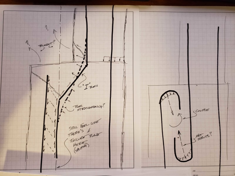
Aside from that, I'd like to discuss a solution for our wall problem here. See below for two questionable details. What is the behavior of such details. Surely someone has come up with a solution for this scenario? The left sketch adds some degree of resistance to the wall splitting in half as discussed. The right side is just me doodling. The splitting issue is not addressed by the right side i dont think.

Another
Strain in the ties as you have sketched in blue in your bluebeam sketch, Koot. You size this using shear friction type equations? Do those equations consider crack width/strain in the tie? I know ACI addresses this as it applies to cracked/uncracked in App. D land. Are there similar provisions for development? Forgive my laziness.

Here are some clips that help express my understanding of development of a bar. Also another questionable sketch:


development1_cwbbap.jpg


development2_nduhw9.jpg


development_im18xx.jpg


Another thread where similar sketches were provided, according to one google search.... [URL unfurl="true"]https://www.eng-tips.com/viewthread.cfm?qid=374061[/url]
 
Want to add a comment about bar spacing too. Thought experiment follows:

Clearly there is a limit we can work from. Consider bar spacing of 1db - this eliminates all tensile capacity of the thickness of the wall. This gets rid of a variable. You're left with the flexural strength stiffness of the two 'lamella' on either side of the curtain of steel that is the 'i' bars coming in from the top to resist the outward splitting forces imparted by the forces emanating from the deformations on the bars.

Incrementally increase the bar spacing. What changes? You gain this tensile 'clamping' force from the concrete along the failure plane. Assume splitting forces remain constant, as if some machine is pulling on each bar with the same force, regardless of spacing. And the same out of plane (soil pressure) unit shear along the stem-stem interface.

We're probably getting lost in the weeds here but the greater the bar spacing becomes, you'll start to have out of plane flexure between the vert bars also. That boils down to a constant unit (shear friction) shear along the 'splitting edge/front edge' of the wall. Essentially saying that shear in the steel is negligible. Which wraps me around my ass to say that the only effect of bar spacing is the reduction in section due to the presence of steel. Assuming the unit shear friction between concrete-rebar is equal to concrete-concrete shear friction.

I've lost my train of thought. Just ginning up some discussion here...
 
Status
Not open for further replies.

Part and Inventory Search

Sponsor