Eng-Tips is the largest engineering community on the Internet

Intelligent Work Forums for Engineering Professionals

Cantilevered Beam Span NDS 3.2.1

Status
Not open for further replies.

Triangled

Structural
Jun 30, 2013
594
0
0
US
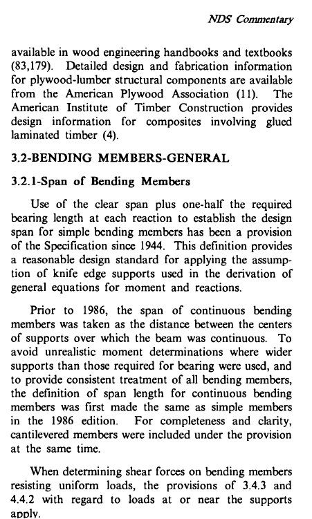
I'm checking some existing glulams, and, ran across the 1986 NDS commentary on 3.2.1 attached, which as far as I can tell, is still appropriate today. I had overlooked this; it is new to me and puzzles me. I ask your help in understanding and appropriately applying.
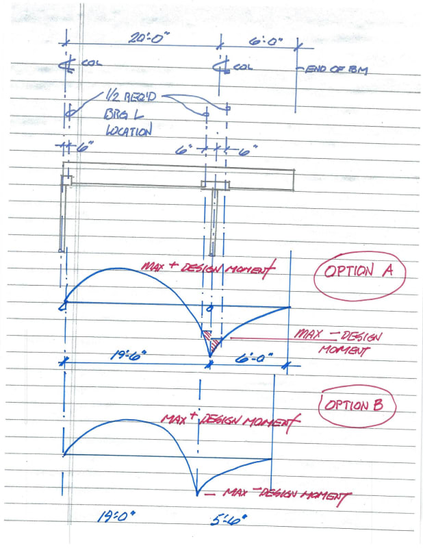
The key item is definition of "span". I am crystal clear for simple span beam. The questions is how to interpret this for cantilevered beam. For years I have adopted the "knife edge" approach at the continuous support. And I do not really understand how to do it any other way. Below the commentary I have appended an sketch illustrating two optional interpretations (perhaps they are both wrong?). Thank you for your consideration.
NDS_Commentary_1986_3.2.1_d1s9k6.png


and here is an illustration showing my dilemma
cantilevered_beam_ss6fj3.jpg
 
Replies continue below

Recommended for you

Agreed with SlideRuleEra. Generally speaking I'm not too concerned about cantilevers in wood framing until the cantilever length is around that 35-40% of the back span. Still check it,but it's not something that flags to me as scary.

The post tensioning idea works for positive bending too. But there are also other alternatives.

The nice part about the post tensioning is it works well on longer spans where adding lumber or steel becomes cumbersome.

Regarding how to ensure a certain tension,I believe you can add inline strain gauges or load cells.

I've seen this employed a few times in older wood framed plane hangers constructed of heavy timber wood trusses.

One thing to keep in mind with this idea, is there may be portions of the beam that become beam-columns and need to be checked appropriately.
 
Post tensioning is a good idea - and may work here. But the cable routing will have to be creative if you have purlins/rafters framing into the sides of the beam.

I have seen where a "post" is added to the bottom edge of the beam near midspan and the cable is routed from one end down around the post and back up to the other end. Haven't designed it myself but ran across it once in a building I was inspecting. Like jayrod12 mentioned, though, be sure you're looking at all aspects of stress in the beam as you'll be changing the nature of the member (post tension force in the cable will need to be resisted by compression in the beam, etc.).
 
Status
Not open for further replies.
Back
Top