Continue to Site

Eng-Tips is the largest engineering community on the Internet

Intelligent Work Forums for Engineering Professionals

  • Congratulations KootK on being selected by the Eng-Tips community for having the most helpful posts in the forums last week. Way to Go!

Cantilevered Retaining Wall Allowable Stress - Using Avg. Stress

Status
Not open for further replies.

Blooongeey

Structural
Jul 3, 2021
20
Neglecting seismic, my retaining wall footing sizes become unwieldy for retained heights around 8' and up. Using 30pcf EFP, it's not unusual to see these footings grow to a width of 6'++ for toe under type walls. I spoke with a well seasoned soils engineer recently who is encouraging me to use "average calculated stress," derived from the typical triangular/trapezoidal stress profile obtained from analysis against the recommended allowable value provided (2.0ksf). This would bring the footing widths way closer to what I believe is practical/realistic/traditional. Anyone else doing this?

Michel
Redondo Beach
 
Replies continue below

Recommended for you

If I understand you correctly you are taking the average pressure on the wall and placing it as a rectangular load rather than a triangular load on the wall? If so, I fail to see how that could possibly yield a smaller footing as your moment should increase as the force at the top would increase.

I have seen truncated forces on retaining walls however, where it goes triangular to a certain depth and then linear the remaining depth, however I wouldn't do this unless the geotech on that specific project told me I could do so.
 
Sorry for the ambiguity .. I am suggesting taking the average of the reaction stress.
 
It's possible that a geotechnical engineer might allow a different stress in the peak value of a retaining wall than for a uniform stress under a shallow column footing. The geotech may want to limit column footing soil stresses for reasons of settlement that don't necessarily apply in the same way to a retaining wall.

A one-third increase or something similar might be appropriate for a retaining wall. I'm not sure I'd just "average" the stress and call it good.
 
A 6' toe for an 8' wall?....Do you mean a 6' heel? Agree with Aesur, don't see how a uniform pressure would help since it would raise the resultant of the force from H/3 above the footing to H/2 above the footing. Not to mention it does not reflect the actual pressure distribution.
 
MotorCity (Structural) said:
A 6' toe for an 8' wall?....Do you mean a 6' heel?
Yes. To clarify, the suggestion from the geotech is to take the average of a 4.0 ksf, triangular reaction stress, and call that 2.0ksf average across the base of the footing, if I am understanding him correctly.
 
the suggestion from the geotech is to take the average of a 4.0 ksf, triangular reaction stress, and call that 2.0ksf average across the base of the footing,

Other than for footings on rock, a uniform distribution of bearing pressure is consistent with the AASHTO provisions for calculation of soil bearing pressure. I believe we use the triangular distribution for the structural design of the toe of the footing.

Capture_swof2r.png


Rod Smith, P.E., The artist formerly known as HotRod10
 
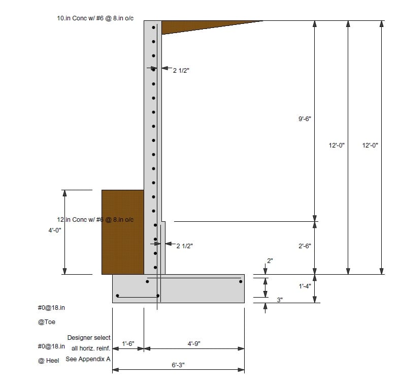
You shall clarify the geometry - toe and heel length and wall thickness, then someone may help. Also, who provided the 30 pcf EFP, and how was it applied?
 
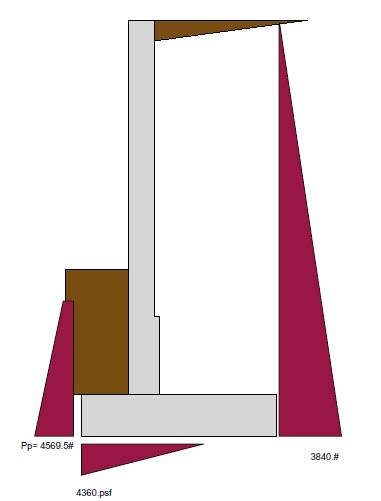
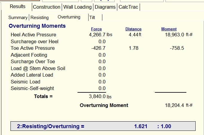
Your active soil pressure confuses me, as p[sub]a[/sub] = K[sub]a[/sub]Γh = 0.33*120*(12+1.33) = 528 psf, and the active force P[sub]a[/sub] = p[sub]a[/sub]h/2 = 528*13.33/2 = 3519 lb/ft of wall, which is located at y = 12.33/3 = 4.11' above the base. Was this the case? Also, the passive force (4569.5#) is approx. located at y = (5.33-1)/3 = 1.44' above the base, correct?
 
Ok, mark that program off my list of software I'd be interested in having. So much wrong with that; where to even start...

The 'extra' #6 bars going straight into the footing are not even close to being developed; neither are the bars in the top of the heel.

We wouldn't even think of stepping the thickness of the stem wall for a wall that size (we've tapered some that were 20'-25' high). The labor to set up the formwork will cost more than the extra concrete.

Rod Smith, P.E., The artist formerly known as HotRod10
 
@BridgeSmith - I believe the image is schematic only and doesn't address development of foundation bars. There is a checkbox in the program to reduce development of vertical bars for the actual stresses. It should also be noted that as far as I know RetainPro was discontinued and merged into EnerCalc now. The step is user input and can be placed anywhere, but I agree, I normally wouldn't step a wall with that height.

It should also be noted that this isn't an 8' retaining wall as initially stated, this is a 12' retaining wall with some soil over the toe, however the soil over the toe does not 100% counteract the soil at the same elevation over the heel, therefore retained height is actually 12' in this case, which is making the 6' heel with 1.5' toe sound more reasonable for a cantilever retaining wall, especially with such high active pressure.
 
The solution sounds right. I think the configuration can work if you can improve the bearing strength to somewhere around 3000 psf. However, I think the 30 pcf EFP is a bit too low, and it is unconservative in utilizing toe pressure in the analysis. I guess the suggestion of the geotechnical guy was based on the redistribution of stress in the soil and subsequent consolidation. I wouldn't count on it, even as it may occur, the wall will have to tilt excessively.
 
The recommended EFP for this application is actually 48psf/f, due to the presence of an in-gound swimming pool above. You are correct that the higher allowable bearing stresses above 2.0ksf will come with additional anticipated settlements, per the geotech ( I am awaiting his amended recommendations still with these higher allowables). What the tolerable settlement for a hillside pool is not clear to me, however.
 
Here is a reminder - you need to provide a drainage layer behind the wall coupled with weep holes to relieve the potential water pressure.

Depending on the distance of the swimming pool, it might exert additional pressure on the wall. Pay extra attention that it can be a killer during a seismic event.


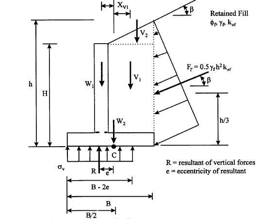
Thank you for the figure. I am not familiar with this approach. Can you clarify the calculation of R & e for a case with 0:1 backfill slope (flat)?
 
Are there any surcharge loadings needed? I would think if this is retaining a pool nearby there is a potential need for surcharge live loading.
 
Aesur said:
Are there any surcharge loadings needed?
The geotech tells me that 48psf/f accounts for the pool. The EFP in locations away from the pool is 30psf/f.
 
@Bloongeey, right, the 48 is a horizontal load, I'm referring to a surcharge loading which is a vertical load due to traffic, live load or other loadings that exerts an additional horizontal loading on the wall. Additionally, how far back is the pool from the retaining wall? There is a possibility that if the pool is close enough there will be an additional "adjacent foundation" load applied to your wall as well.

This Link has some information on surcharge loading and how it applies to the wall.
 
Status
Not open for further replies.

Part and Inventory Search

Sponsor