Continue to Site

Eng-Tips is the largest engineering community on the Internet

Intelligent Work Forums for Engineering Professionals

  • Congratulations SDETERS on being selected by the Eng-Tips community for having the most helpful posts in the forums last week. Way to Go!

Capability Study - Virtual Condition Boundary method

Status
Not open for further replies.

Kedu

Mechanical
May 9, 2017
193
Does anyone know (or maybe has an article to post) on how to do a capability study on position tolerance at MMC callout using "Virtual Condition" boundary approach?
As far as I remember, and read, this method has been developed (and shown) by prof. Don Day few years ago.

Few questions came in my mind:
- is the capability study done on "the combo" size and position instead of position alone?
- in order to use known Cp, Cpk formulas, do size and position should be independent?
- is feature's size variation taken in consideration when "VC boundary" method used?

 
Replies continue below

Recommended for you

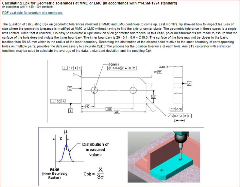
I found this online, but still not clear and not able to answer the questions above..
Will the calculation method be different if 2009 version is used?
I really appreciate if someone can provide detailed instructions on how to understand and apply in industry the concept below
VCB_-_Copy_cfdyni.jpg
 
Kedu said:
- is the capability study done on "the combo" size and position instead of position alone?
- is feature's size variation taken in consideration when "VC boundary" method used?

While the size of the virtual condition for position tolerances at MMC (or LMC) is calculated by combining the size of the feature and its position tolerance, what really matters in the process capablity study for the the boundary method is the location of the actual surface of the feature relative to the virtual condition. Determination of the actual surface location is done without a need to separate feature size variation from its position variation.

For example, if we consider the drawing and the approach used in the tip, a workpiece with the actual hole produced at dia. 19.9 and perfectly located at its true position will give the measured value of R9.95 (19.9/2). The same measured value of R9.95 will be also obtained if another workpiece has the actual hole produced at dia. 20.0 with the actual position error of dia. 0.1 (0.05 off of the true position). This basically means that from the boundary method standpoint the two holes are equal - in both cases the smallest distance between the surface of the hole and the virtual condition boundary is 0.3 (R9.95 - R9.65), even though in both cases the holes have definitely different actual sizes and positions.


Kedu said:
- in order to use known Cp, Cpk formulas, do size and position should be independent?

Based on my limited knowledge of statistical distributions I would say that the known formulas for Cp (Pp) and Cpk (Ppk) will work only if the distribution of the measured value is proved to be normal. For nonnormal distributions other methods / formulas to calculate the process capabilty indices have to be used.

Kedu said:
Will the calculation method be different if 2009 version is used?

I don't think the calculation method for the boundary approach will be different if Y14.5-2009 is used.
 
One of the best explanations I've found for this is an SAE paper by a GD&T colleague, Dan Bauer. I don't think it's free, but it might be worth the purchase if you a really interested in the topic:

[URL unfurl="true"]https://www.sae.org/publications/technical-papers/content/2009-01-1546/[/url]


John-Paul Belanger
Certified Sr. GD&T Professional
Geometric Learning Systems
 
I would assume that most methods for directly calculating process capability for MMC position (that actually want to take advantage of the additional tolerance afforded by MMC as well as protect VC) would involve actual value for MMC or some variation thereof which combines size and position deviation. Ie: since for the surface interpretation an internal feature actual_value = size_MMC - size_RAME which can be compared to the tolerance value t_0 in the FCF, if you're actually interested in the radial distance (minimum distance/clearance) from the feature to virtual condition then your calculation would be radial_distance = (size_RAME - size_VC)/2 = (size_RAME - size_MMC - t_0)/2 . Of course a similar calculation could be made with coordinate/axis data* and the axis interpretation with the knowledge that the two calculations have the potential to deviate with increasing form/orientation error.

When it comes to actually monitoring the process and making adjustments to meet process capability requirements actual value and the related minimum distance from the feature surface to the virtual condition boundary alone don't tell you much about what knobs to turn. The attached article might be an interesting read. It focuses on two companies that disagreed over rejection rates because one was checking with attribute gauges (combines position/size and bonus tolerance into a pass/fail surface check) vs SPC (variable position/size data considered independently - essentially RFS without bonus) - the end of the article shows how the company was able to use the independent variable position and size data (without bonus tolerance) to shift the process to bring the process capability calculated with combined position/size data (including bonus tolerance) to the level required by their customer.

Admittedly I am not a statistics expert and the article definitely gets into the weeds a little, however even without the in-depth calculations there are some interesting conclusions.

Also the same author as the article (Paul Jackson) has quite a few forum posts on this topic, one of which he shares some of his spreadsheets for Ppk calculation based on measured position/size data.


*For the axis interpretation of an internal feature it would be radial_distance = (size_UAME - D - size_MMC - t_0)/2 where D is the amount of position deviation of the UAME axis.
 
Wow, …threads and discussions referenced have been an interesting reading for me for the last couple of days. Thank you chez311
Looks like there are multiple methods developed and no consensus…
I also ready some discussions here on eng-tips about the very same topic.


pmarc and J-P,


Side note: I know I pick on you, as this is because at least two reasons: you were involved in the discussion with Paul Jackson (referenced thread) as well in this thread and –the most important one—your level of expertise and appreciation I personally give to your opinions…

Two of my questions (and I hope the OP won’t mind hijacking his thread just a bit) are:
1.) What are the disadvantages/drawbacks of Don’s Day VC method?
2.) For non-normal distribution (and I think position at MMC is a non-normal one being highly skewed) what would YOU recommend: distribution transformation (ex: log distribution) or using different Cp/Cpk formula/ adjusted formula and how would you adjust it? The same way shown in Paul Jackson’s pdf (Expanding Limits SPC)?

Happy Thanksgiving everyone!


greenimi,

Great find as well! Looks like he was also a contributor here, and involved in a discussion with active members here.

Reading through that thread it occurs to me why the (x,y) coordinate method is so common for the measurement of hole position - it seems that perhaps often it is assumed that a single measurement is sufficient and the axis assumed perfectly oriented and the size of the UAME the size of the inscribed/circumscribed (for internal/external feature) circle from the measured points. For a CMM I agree with pmarc's statement (1 Jun 11 17:34) that measurements at several points along the feature's length should be ideally taken - I would think at minimum at each extremity (ie: top/bottom of a hole - 3x including a midpoint measurement if at all possible). This is what has always bothered me about seeing just (x,y) coordinates and assuming perfect orientation of the measured axis - if it is taken from a measurement at only one point along the feature's length I think that leads to some potentially problematic assumptions about the orientation of said feature, especially as the length to diameter ratio increases - for both MMC and RFS controls.

The strange thing is that these two statements are found in the same post:

Your objection to the analysis procedure is... that it does not confirm that the maximum material boundary is not violated when only a sampling of the feature's surface is used to generate data about its size and location... specifically disregarding its possible orientation deviation. Did I get that right?

So what!

[...]

If I was checking a bore and I suspected that it was particularly vulnerable to an orientation deviation according to the observed process and I wanted always to use its "related actual mating envelope" in my variable limit position tolerance capability calculations... and I had not yet programmed that routine in my software... I just might move reference to one end of hole rotate orthogonal to the hole's specified orientation, collect three eight point circles top, middle, and bottom, then use all 24 point's X and Y values stripping off the Z (depth) values to figure a 2D maximum inscribed circle size and location to use in my capability equation.

I reckon he could have just lead with the latter statement and left out the "so what". Though how does one know to be concerned abut orientation if its not measured? Perhaps through either some knowledge of the process or a company "best practice" based on length to diameter ratio - seems like quite a few assumptions going into that.

A great quote from JP in the referenced thread:
Peter, while I sympathize with the dilemma, it sounds like you're letting the inspection method (and tracking thereof) define the product requirements, not the function.

From Dan Bauer's article:

Dan Bauer said:
The CpkVC method has been tested, corroborated, and verified using actual production data and experience as well as extensive statistical simulation. Multiple combinations of size and geometric error simulating various normal and non-normal distributions have also been used to test and validate this method. In all cases the method has been shown to be solid and reliable.

JP or pmarc - thoughts about use of the virtual condition/boundary method and Cpk (or CpkVC as Dan calls it) on non-normal distributions?
 
greenimi said:
1.) What are the disadvantages/drawbacks of Don’s Day VC method?
I don't really see many.

I can imagine that some may say that it doesn't give any data as to where exactly (in terms of x, y coordinates) the actual hole is relative to the true position, therefore it is hard to tell exactly how the process should be improved, if improvement is needed. But as I tried to explain to Paul Jackson in that old thread (and as Dan Bauer says in his paper), this information may not necessarily be needed to have well capable process from the perspective of ultimate goal, which in case of positional tolerancing at MMC usually is proper assembly.

The other problem, which I already mentioned too, is that the collected data may not be normally distributed and therefore the commonly known formula for Cpk (Ppk) may not be applicable that easily.


greenimi said:
2.) For non-normal distribution (and I think position at MMC is a non-normal one being highly skewed) what would YOU recommend: distribution transformation (ex: log distribution) or using different Cp/Cpk formula/ adjusted formula and how would you adjust it? The same way shown in Paul Jackson’s pdf (Expanding Limits SPC)?

chez311 said:
JP or pmarc - thoughts about use of the virtual condition/boundary method and Cpk (or CpkVC as Dan calls it) on non-normal distributions?

I am not an expert in statistics and that is why I am not really sure what the right thing to do is in case of non-normal distributions. I found, for example, the following article on the web:


I believe it quite nicely describes the risk of using traditional formulas for capablity indices in case of non-normal distributions, although they could probably do much better job in explaining where the other formulas came from and what they really meant.

Finally, I think that it is worth to mention that both, Dan and Paul, used x and y coordinates of the centers of the features as an input for the calculation of Cpk (for that reason they also needed to assume perfect orientation of the features). In Don's approach (and according to the boundary interpretation of position at MMC) the information about location of the center of the feature is not needed at all. All that matters is where the worst-case point on the surface of the feature is relative to the virtual condition/true position.
 
I will simply echo Pmarc's last post, since I've not really studied the given method(s) for non-normal distributions.

John-Paul Belanger
Certified Sr. GD&T Professional
Geometric Learning Systems
 
I can imagine that some may say that it doesn't give any data as to where exactly (in terms of x, y coordinates) the actual hole is relative to the true position, therefore it is hard to tell exactly how the process should be improved, if improvement is needed.

I would have to imagine that measurement data can produce both metrics - those needed for capability per the virtual condition/boundary method while still producing independent position/size/orientation information to be retained and analyzed separately for process monitoring, right?

I wonder what causes such aversion to consideration of orientation? Perhaps it comes from a perceived difficulty in separating orientation error from position error? It seems to me it could be done in such a way that everyone is satisfied while collecting enough data to take into account orientation error.

Axis Interpretation
d = diameter of orientation constrained axis containing envelope
(x_d,y_d) = x and y coordinates of d relative to true position
D = diameter of location and orientation constrained axis containing envelope

Surface Interpretation
d_o = diameter of orientation constrained RAME
(x_o,y_o) = x and y coordinates of d_o relative to true position
D_TP = diameter of location and orientation constrained RAME (2*r_TP the "true position mating size" per Y14.5.1-1994 or what I was previously calling size_RAME)

values for the VC/boundary method could still be calculated as:
radial_clearance_axis = (size_UAME - D - size_MMC - t_0)/2
radial_clearance_surface = (D_TP - size_MMC - t_0)/2

Utilization of either (x_d,y_d) for axis or (x_o,y_o) for surface would provide the (x,y) coordinate data for continuous process monitoring of position, and evaluation of d (axis) or the difference between d_o and size_UAME (surface) would provide orientation data for continuing process monitoring of orientation. If you wanted to really go wild the UAME axis could be converted into a vector projected onto the (x,y) plane which could be utilized to show the "direction" of the UAME axis orientation error to see if theres a bias or pattern to the deviation which could be addressed in the process. Quantitative analysis of this might be a little more difficult but I would imagine doable - graphical visualization might be easier.

Perhaps the surface data is not as useful as the axis data for process monitoring, however it seems to me that if this information is available (surface data) for virtual condition/boundary method capability analysis that the axis data can be relatively easily derived.

Thanks also for that information on non-normal distributions, I'll definitely have to dig into that more. Looks like at least Paul Jackson mentions a box-cox transformation in his presentation for dealing with non-normal distributions.
 
Status
Not open for further replies.

Part and Inventory Search

Sponsor