Burunduk
Mechanical
- May 2, 2019
- 2,513
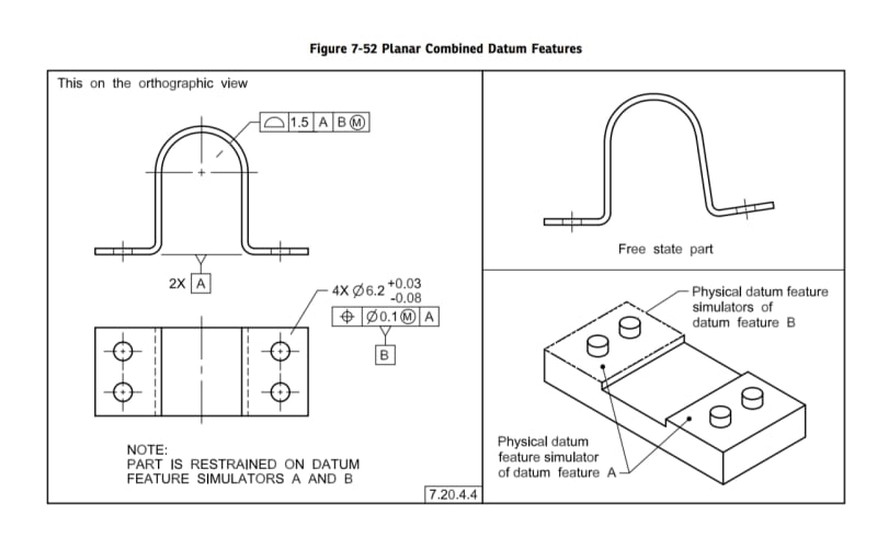
According to sub-paragraph 7.20.4.4 in ASME Y14.5-2018, datum features of size referenced at MMB can participate in restraining the part (producing a restrained condition). The sub-paragraph refers to figure 7-52, which doesn't include a detailed restraint requirements note (a detailed note is available in figures such as 7-27 and includes mounting instructions with fasteners and torque data).
Does anyone have an idea, or can provide an example, of how the four pins used as datum feature simulators of datum feature B in figure 7-52 can be used to apply forces on the part?

Does anyone have an idea, or can provide an example, of how the four pins used as datum feature simulators of datum feature B in figure 7-52 can be used to apply forces on the part?
Y14.5-2018 7.20.4.4 said:It may be necessary to use multiple features of size to establish a datum reference frame when a restrained requirement is invoked. For the datum features to comply with the physical datum feature simulators, forces may be applied in accordance with the specified restraint requirement to flex or deform the part. See Figure 7-52.
NOTE: The position tolerance shown in Figure 7-52 for datum feature B (pattern of four holes) is not used to determine the free state location of the holes. It is used to establish the MMB simulators that are to restrain the part to simulate the installed condition


