Eng-Tips is the largest engineering community on the Internet

Intelligent Work Forums for Engineering Professionals

  • Congratulations waross on being selected by the Tek-Tips community for having the most helpful posts in the forums last week. Way to Go!

Cast steel part fracture, thoughts? 2

Status
Not open for further replies.

emonje

Mechanical
Nov 3, 2006
48
0
0
AU
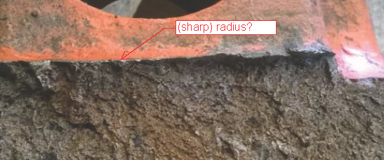
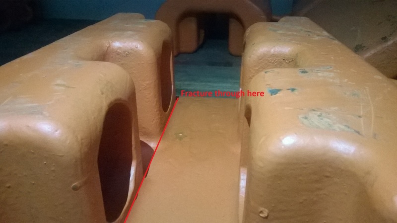
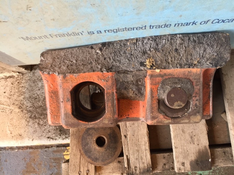
Several of this part failed recently, all breaking apart at roughly same area.
It's made of cast steel (C 0.27%, Mn 0.9%, Si 1.4%, Ni 0.75%, Cr 1.85%, Mo 0.4%; Hardness 43-45 HRC).

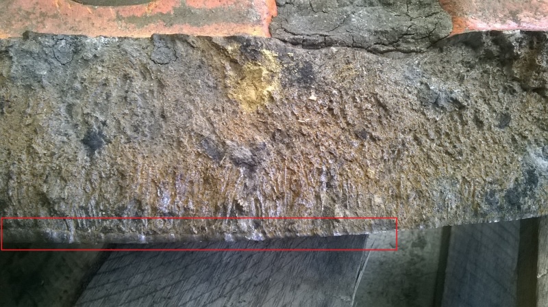
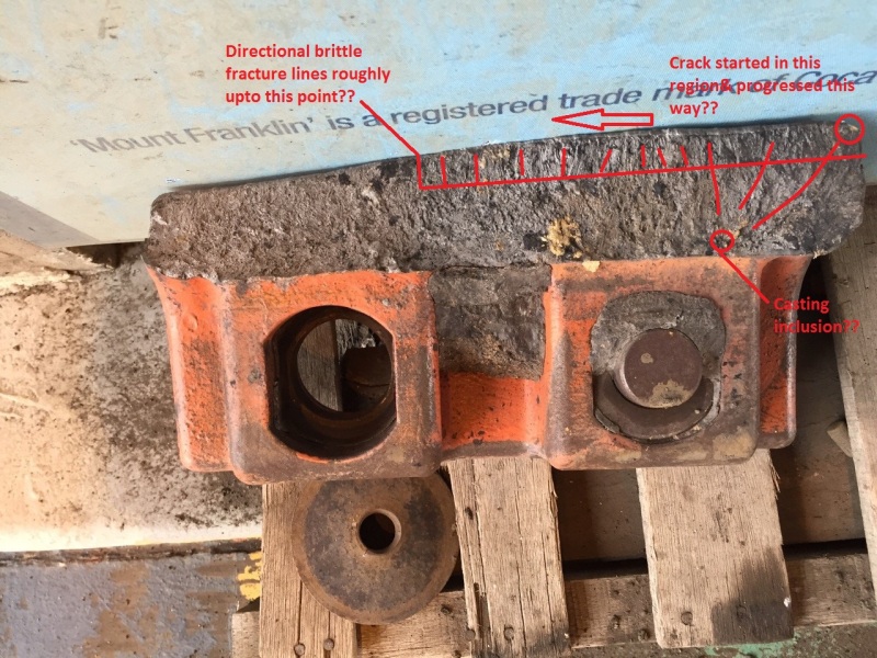
Just got this one piece here this morning, I'm not sure if I'm reading it right trying to guess something from the fracture surface.
We are sort of based in wilderness so any kind of test will take some time. Before that happens can I please have your thought on this?

CS180_huuuya.jpg

CS180_210916-1_f14y74.jpg

WP_20160923_003-MOD_dtjxuw.jpg
WP_20160923_007_favl1l.jpg
WP_20160923_011_iebwbz.jpg
WP_20160923_010_gs6wrf.jpg


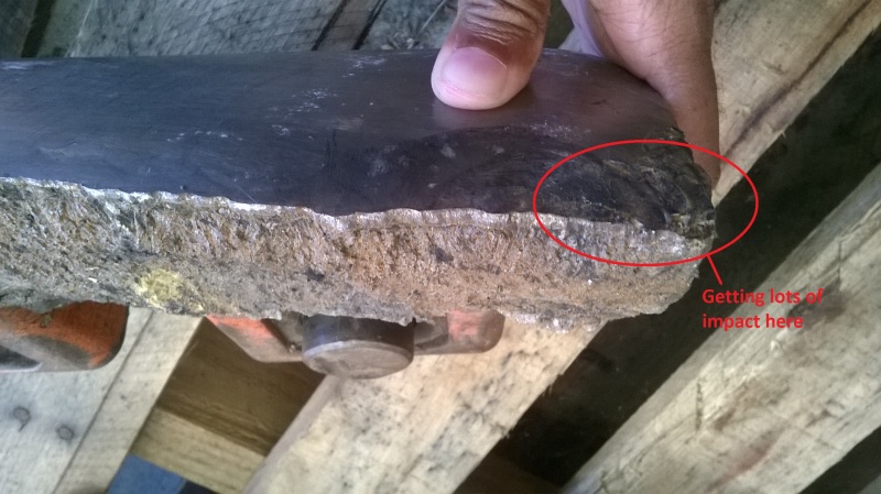
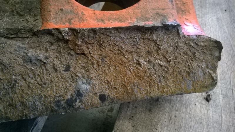
Operating conditions had changed & we are guessing the parts started taking lots of impact on area as seen on 3rd image which is causing the fracture.
Or is there anything else involved as evident from the fracture face that I'm missing?

Thanks & Regards
 
Replies continue below

Recommended for you

With changed op. conditions you might say that load has increased or direction of load has changed? If so, you may want to check whether the loadbearing capac. of the cross section is still sufficient. It seems, that the part fractured at a section where there's a geometric stress raiser at least on the upper side:
rad_ocfv4i.png

Also, the different colouring of the fractured surface might indicate a progressive instead of a instantaneous fracturing, so perhaps you can investigate more deeply on the origination of fissures.
This type of layer in the structure of the cast looks strange to me, did you some welding or material buildup?
lay_fqvlct.png

Finally, the very edge of the "space under impact" in your 3rd pic very much looks as if there's been made a deep notch = fracture starter. Any chance to change this situation?
Kind Regards


Roland Heilmann
Lpz FRG
 
I would look at stress raisers due to change in geometry and any cracks during quenching and tempering. Relook at tempering cycle and provide a generous fillet radius ,not seen in the pictures.
Brown color area might be due to cracking during quenching. A microstructure report will be helpful.

"Even,if you are a minority of one, truth is the truth."

Mahatma Gandhi.
 
The part is designed as a wear protecting shroud so basically not carrying any load.
It is expected to get hit by chain links & similar at random interval but we are guessing for a week or so frequency of impact increased by quite a bit.

WP_20160921_004_of7u25.jpg

This is a weaker point where you might expect failure to start if pushed to the limit, not clear in the photo but corners have 10 mm radii.


WP_20160923_009_sdraqz.jpg

This layer got us baffled too but forgot to mention. There was no welding or build-up done on this. Can it be inadvertently case hardened while heat treating after casting?

Thanks & Regards
 
It could be a hot tear, which escaped notice and now manifested into a crack. Review the complete casting process, before any conclusion.

"Even,if you are a minority of one, truth is the truth."

Mahatma Gandhi.
 
Emonji,

I think you have your fracture initiation/propagation direction wrong in the 2nd photo of your original posting, and that is messing you up.

It looks like you have 2 distinct crack initiation areas, both at the lugs at the bottom of the first photo. The fracture propagated through thickness from the lugs. The lug on the right looks like the first place where fracture initiated as this area is larger. You can see fracture flow lines kind of radiating from that surface that have a large, almost through-wall thumbnail shape. Look especially atthe right side where another thumbnail is located at the lug surface. You should first focus on this region.

I would suggest you have someone experienced in metallurgical failure analysis perform an evaluation (including SEM fractography and metallography) so you can evaluate possible causes properly, including whether casting imperfections are present and whether they are the cause of fracture.
 
Judging from the size of your thumb in the photo, there interior of the casting looks more like foam rubber. Lots of voids, internal failures and coarse grains.
 
There are four locks that sit inside those four cavities, with studs protruding inwards
WP_20160923_005-EDIT_xwot4u.jpg


The protruded part sits inside a groove & keeps the part from dropping. The part sits sloppy, it is not tightened against anything.
 
Emonji,

The outer layer you show that has you baffled would coincide with the final fracture location - the difference in morphology may be as simple as that. This particularly makes sense if this was a fatigue failure where you have very little steady state stress from what you described. Again, a proper metallurgical failure investigation will confirm if this is final fracture or if the layer was representative of a different source (such as welding).

Your description, "The part is designed as a wear protecting shroud so basically not carrying any load", is important because some source of loading had to be present to induce fracture. That is worth thinking about in figuring out root cause.
 
Status
Not open for further replies.
Back
Top