Continue to Site

Eng-Tips is the largest engineering community on the Internet

Intelligent Work Forums for Engineering Professionals

  • Congratulations waross on being selected by the Eng-Tips community for having the most helpful posts in the forums last week. Way to Go!

Casting failure

Status
Not open for further replies.

emonje

Mechanical
Nov 3, 2006
48
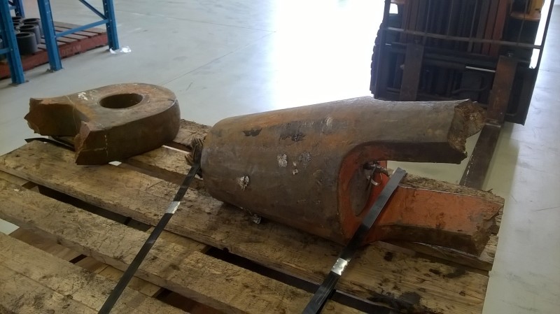
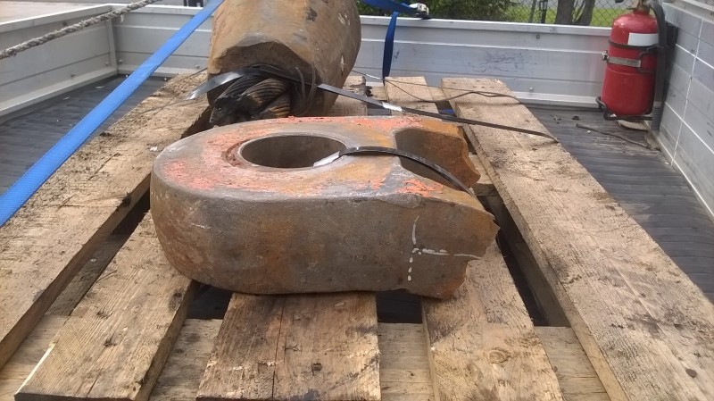
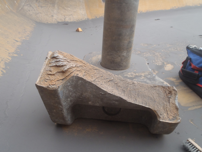
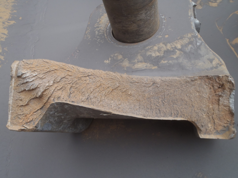
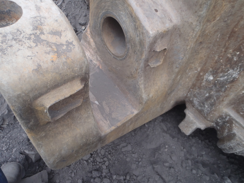
This is a cast steel spelter socket. Failed after 24 hours of service.
Trying to guess what might have been the issue before sending out for tests.
untitled.8_iobo09.jpg

WP_20161222_09_56_25_Pro_sq5w63.jpg

WP_20161222_08_08_27_Pro_e1qemb.jpg

WP_20161222_08_08_33_Pro_bkhinf.jpg

WP_20161222_08_05_05_Pro_mmv0g3.jpg

WP_20161222_08_05_12_Pro_nvzhrt.jpg


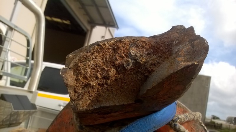
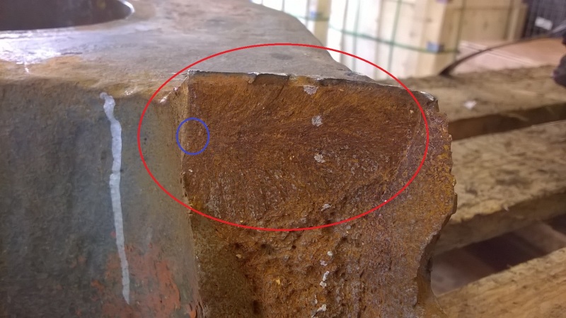
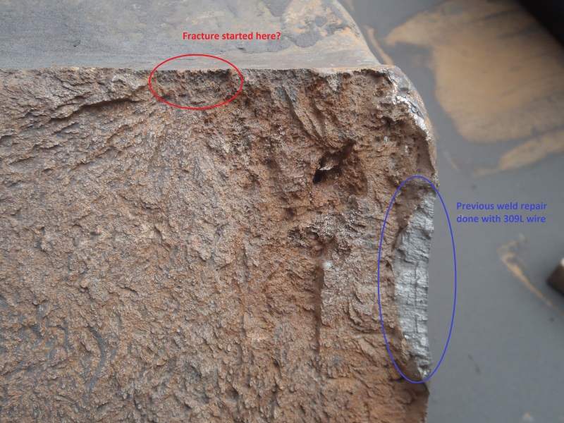
Fracture started here??:
WP_20161222_09_55_59_Pro_EDITED_mysgbu.jpg

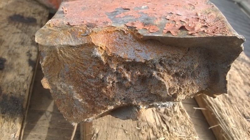
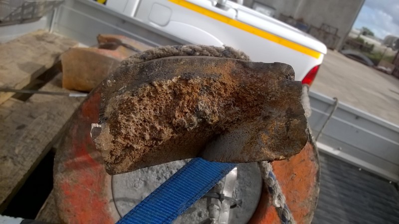
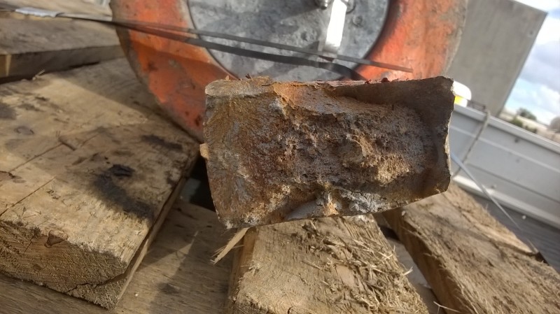
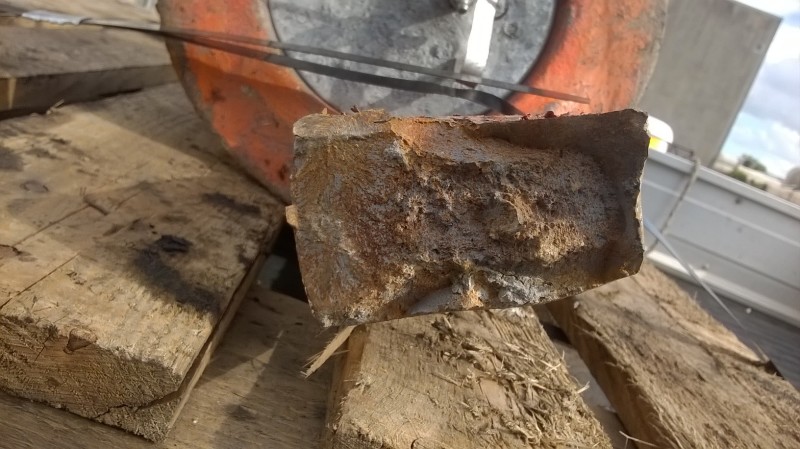
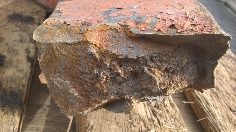
Other side of the same leg. Gas porosities??:
WP_20161222_08_08_33_Pro_ezxswz.jpg
WP_20161222_08_05_12_Pro_rxmw0c.jpg


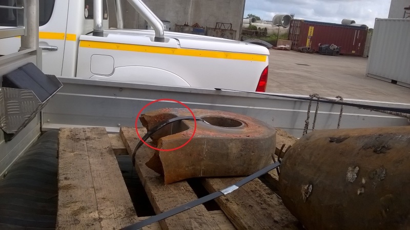
The legs are bent, yielding after fracture??:
WP_20161222_08_06_30_Pro_EDITED_x09bwx.jpg

WP_20161222_08_09_08_Pro_n1sr5v.jpg


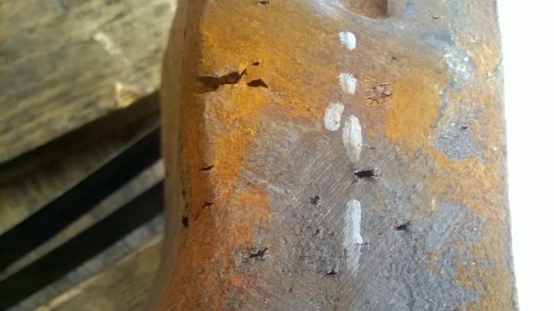
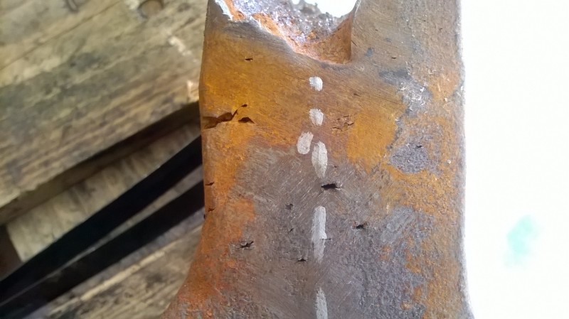
Also these opened up on one of the legs:
WP_20161222_12_08_20_Pro_oxsnrh.jpg

WP_20161222_12_08_26_Pro_zz6r4t.jpg


Any observation is highly appreciated.

Thanks.
 
Replies continue below

Recommended for you

Two observations; the fracture initiation site you pointed out for the eye in one of the slides looks correct. Second, this appears to be a ductile overload event based on the appearance of extensive local plastic deformation. The hole in the eye hook looks elongated.
 
What is the type of cast steel material? Was is used as cast condition or heat treated?
 
Thermal history of the casting is necessary. The defects seen reveal that the foundry has very little process controls. Thus, anything is possible.

"Even,if you are a minority of one, truth is the truth."

Mahatma Gandhi.
 
Looks like overload failure, casting seems to have lot of defects.
 
Why wasn't this produced from a forging instead?

Maui

 
Does it look weld repaired to anyone else? Difference in flash rush, evidence of grinding, and of course a lot of little porosity around it. Any sort of NDE? Mag particle?
 
"Why wasn't this produced from a forging instead?"

This is fairly typical "Steel forgings are used on rope sizes 1/2” through 1-1/2” and cast steel fittings are used for larger sizes."

Note a spelter socket grips the rope via a poured zinc or epoxy "socket" .
 
The fitting is clearly bent indicating that the load on it was in a direction it was not designed for.
 
Thanks.

Steel is 0.2%C, 1%Mn, 2%Ni, 1%Cr.
Quenched & tempered to 650 MPa yield strength & 25 HRC.

Mag particle & RT was done by the foundry.
I am yet to get the radiographs but they say they had category II gas porosities (ASTM E186 & E280) in region where it failed.

There are two of these rope-socket assemblies in the system. When this one snapped the other one carried the entire load until they could lower it down after quite some time. I don't have that other socket but site guys say it was fine & they didn't see any deformation on that one.

 
My observation:

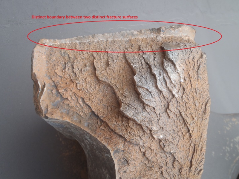
I agree with crack initiation site. Also around that as you pointed out by red oval, looks like fatigue clamshell marking to me. There might be a porosity or casting defect that act as stress raiser and initiate the crack. Cyclic loading (?) assists with crack propagation till fracture. Also based on the plastic deformation, I think the part has experienced some shear stress or less likely yielding after fracture. If it supposed to face that kind of loading, Based on the part shape, it could have been designed differently.
 
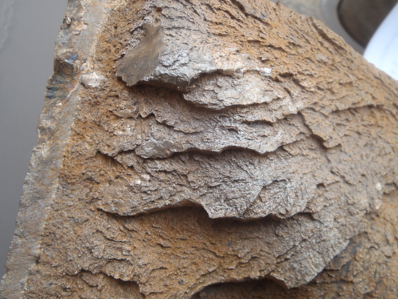
The fracture surface at the initiation side looks like cheveron pattern with the V pointing to the initiation site as indicated in oval. The fibrous fracture surface at the bottom is due to overloading. The 45 degree angle to tensile loading direction where it has the maximum shear stress. It is very interesting to look at closely at the initiation site for defect and do some fractography by scanning electron microscope (SEM) attached with EDS for the chemical analysis at the initiation side.
 
You do need some analysis. The initiation site should be evaluated in an SEM to determine fracture mode since fatigue can appear like overload or rapid fracture to the naked eye. An overload should be pretty clear if that was the mechanism. Make sure to look at it both before and after cleaning. Then section through the origin - if excess porosity was the cause, it should be very clear. Good luck!
 
The kind of defect shown in photographs, is a matter of concern. Such a defective casting should not have left the foundry, nor should it have been accepted by the end user. A serious nonconformance at both the ends risking lives and property.

Let us foundrymen, be more responsible ,else we start hearing from competition, "Why castings?" .

"Even,if you are a minority of one, truth is the truth."

Mahatma Gandhi.
 
Was it overloaded, or just a "normal load" that did NOT exceed design limits for 100% capacity?

If a "normal load" was on the hook - did it get a jerk or impact, or a steady slow increase as in a normal lift?
Any chance the load had jammed or fouled a cable, pulley or sheave so the "load" was as expected, but the crane was actually trying to pick up two or three times the expected force?
 
Where was the failed component made ?

MJCronin
Sr. Process Engineer
 
I also noticed multiple cracks adjacent to the fracture, one distinct one on the corner parallel to the origin and others in the interior. I think these wold have formed over time, most likely by fatigue. I wold be particularly interested in looking at porosity as your root cause. Also, does your system include loading in the direction of bending during service? As others have pointed out, this may be a clue if you do not have such lateral bending.
 
It looks like it caught on the shoulder on one side causing an off-center pull. I would not be surprised if the operator gave it several extra tugs to try to break it loose.

If this was a straight pull and one side gave way before the other, the bend of the secondary failure leave that side flat and bent outwards, but it looks like both sides are bent to the same side indicating they yielded in bending before failing in tension.

Overall it looks like a poor quality casting, but one that should be over-designed for the use and that it was abused.
 
No matter how good the design, excess porosity (if present as I suspect) will compromise the structural integrity whether it was abused in operation or used as expected.
 
Thank you very much for the valuable comments, much appreciated.
Testing services are just starting to open their doors after holidays, I'll be visiting them soon with this.

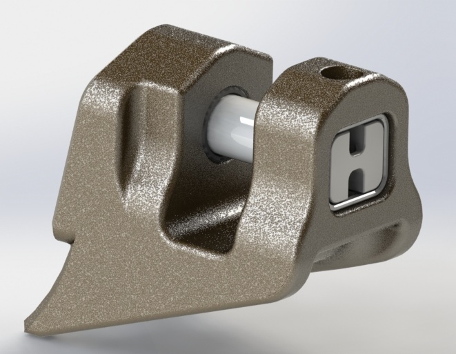
Meanwhile, as a part of universal conspiracy to ruin my vacation another casting failed over the holiday break.
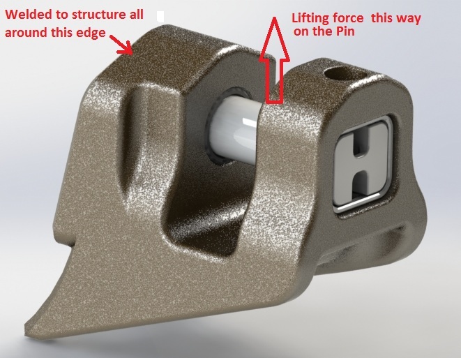
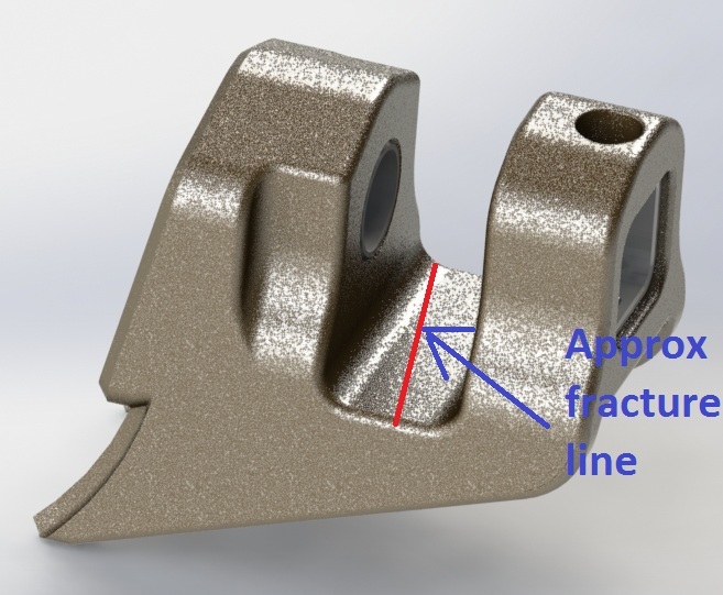
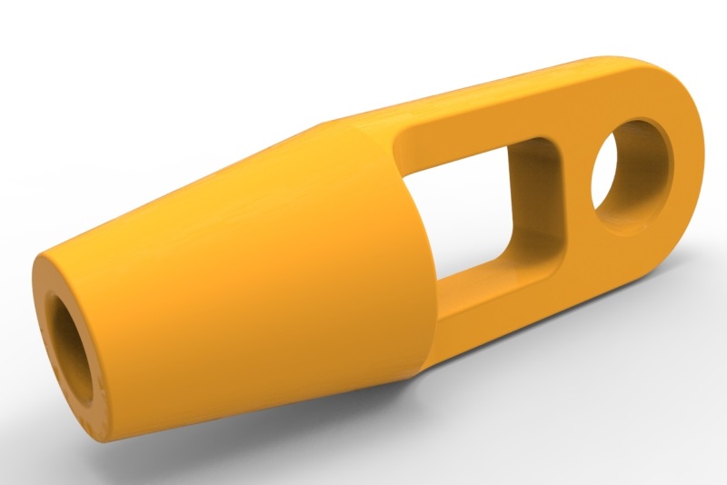
This newly failed casting is linked to to above casting through another cast link.
TB_RENDERED_ozsn6d.jpg

TB_RENDERED_EDITED_d0njrq.jpg

TB_RENDERED_02_qo7tdf.jpg


Here are the shots of fracture surface:

PC300204_lphkyz.jpg

PC300207_ltdnqn.jpg

PC300194_hdlzrm.jpg

All these ridges and facets, does this look like "rock candy" fracture? I'm thinking of asking for Al and Boron content tests.

PC300205_EDITED_rynqod.jpg

PC300208_EDITED_sim1rt.jpg


PC300214_daqlyf.jpg

Other side survived.

Thanks for looking & your comments highly appreciated.
 
Status
Not open for further replies.

Part and Inventory Search

Sponsor