Eng-Tips is the largest engineering community on the Internet

Intelligent Work Forums for Engineering Professionals

Catia V5 Drafting Mode 2

Status
Not open for further replies.

LakeErie

Automotive
Feb 14, 2011
6
0
0
US
Hello Catia users

My name is John. I work in an Aerospace facility. This company recently purchased Catia V5 revision 18 or 19 I don’t recall off hand. For my questions this change in revision levels should have no effect. I have been using 3-d modeling since 1998 (college) and 2000 (industry). In industry my predominant use was in UG and Solid works. I like all other users in different software packages look for similar features to accomplish engineering tasks and projects.

After completing a product assembly, can I complete the following? (Switch to drafting workbench)
1. Create view 1 with all components shown.
2. Create view 2 with components hidden, not shown, inactive or whatever terms may be used in Catia.
Modify the assembly (product) remove components, modify geometry etc… Rebuild product and drawing to reflect changes.
3. Can I maintain view 1 rebuilt reflecting these changes?
4. Can I maintain view 2 rebuilt reflecting these changes?

An example would be if I had a top die assembly and a bottom die assembly.
View 1 = top and bottom dies shown.
View 2 = top die assy. components shown only.
View 3 = bottom die assy. components shown only.

5. In the drafting workbench under each view can I view the entire tree of components used to create each view? Select, show hide etc….

After modifying the product I should be able to maintain the links for all 3 views and have them update accordingly. Right now I create view 1. Hide components for view 2 (in product mode) and then on my drawing view 1 now falls apart showing of course view two. My solution is it isolates views after creating them but this really sucks. Please help.

Thank you
John


Replies continue below

Recommended for you

There are a couple of ways to do this but the function that I think is the most applicable is the "enhanced scenes" function in the assembly workbench. What you want to do is highlight all of the components in the tree that you want to be included in a particular view (ctrl+select, shift+select to get everything you need) and then choose Insert=>Enhanced Scene (I'm not looking at CATIA right now so exact name of command might be slightly different.) You will be asked to name the scene and choose between full and partial overloading. I always choose full, but I don't have a full understanding of what the difference is. Perhaps someone else can elaborate on that point. You will now be launched into a new viewing environment with a different colored background and only the components that you had selected will be visible. In this new environment you can move the components around to create an alternate arrangement, an exploded view, or whatever else you may want to do. When you are finished click on the exit icon (same icon as used for exiting a sketch.) You will now return to the main assembly view and all components will be visible and in their original locations. You will notice that a new leaf has been added to the tree called "scenes" and your new scene can be accessed under that leaf. When you create your drafting view you need to select that scene from the tree. Now your drafting view will be insulated from any hide/show actions or other modifications made to the main assembly view and will always show the assembly as you had defined it in that scene. Beware, however, that if you add new components in the future there is NO WAY to add them to an existing scene. You will need to create a new scene that includes the added components and then create a new drafting view from your new scene. This is a major limitation of the scenes function and there is no way around it that I know of. Perhaps it is possible to add a few empty parts as placeholders and then use the "Replace Component" function to replace them with future additions if necessary.

Hope that helps.

CATIA V5 R20
PC-DMIS 2011 MR1
 
John,

Your company made a big investment in CATIA. Hopefully they also purchased some training inorder to maximize their investment. If not, your company is wasting alot of time and money! In class, you will learn how to do all the steps above. (just let the instructor know this ahead of time)

The company that sold CATIA should be able to come to your office and show you and your design team how to accomplish the steps you have listed. It would be much better to have someone show you the process in person and answer any other questions. This would be more efficient then relying on forums such as this one.

Jack
 
Hello Jack

Thanks for the advice. We had five of us in a short training class. By Friday afternoon the other four were literally sleeping. I was the only employee that was awake. Since they all feel the Product Mode is a waste of time they caught up on needed rest. They build each component of an assembly in one part file (multiple bodies in one part file) using translate, rotate etc... Any change to a part creates big issues and all of the drawings are falling apart. Future employees will have no idea how dies were cut since rebuilding a drawing shows a completely different drawing of the current showing components. My questions are to educate myself since I enjoy learning and doing things correctly. In the future if I’m required to clean up the mess that is being made I want to have a plan of action. Otherwise it’s good practice and education for my future career path. I would not set up a cad system for a 50 million dollar corporation based on tips and tricks from a website. The people on this site in many instances have clever insights and methods for solving problems. Again thanks for the advice.

Thank you Dasalo for the help you provided in your post. Scenes were used many years ago in other packages. So this helped put me on the right track.

John
 
John,

Thanks for the reply, and I'm glad to hear you and your co-workers did get some training. I suggest you get in touch with your instructor and ask him/her for their suggestions to your drawing questions.

Scenes are definitely one method to show different components of an assembly. But, Overload Properties is another method that might be better in your situation to show/hide various components in different drawing views. For your co-workers that insist on making assemblies with Bodies in a Part, Modify Links can be used instead of Overload Properties.
 
Hello Jack
Thanks for the help.

For your co-workers that insist on making assemblies with Bodies in a Part, Modify Links can be used instead of Overload Properties.

I tried this Part Modify Link in the drafting mode but it is grayed out. Maybe I don't have the rights to acomplish this ?

John
 
Modify Links is part of the Generative Drafting workbench, and doesn't require anything special. But it's not the most intuitive thing to use.

Start with a normal drawing containing several views of a 3DCATPart. The top section of Modify Links will show you all the Bodies that are "pointed" (currently used to define the view). You can select one or more Bodies and Remove them if there are Bodies you don't want to see in that view.

Adding more Bodies isn't that easy:
1. right-click on the view and select Modify Links
2. change window to the parent 3D CATPart
3. select the Bodies to be added to the view
4. return to the drawing window, and note the lower section (3D elements to add)
5. click the ADD ALL button to move them to the Pointed Element section
6. click OK
7. Update the view to see all the pointed elements in that view

Use Apply Links To to copy definition to other views

 
Just to add to what Jackk said, you can also do this right from the get go when placing new views, for cases where you have all the different bodies in one CATPart. For example: Place new front view, window over to your 3D part, but BEFORE selecting anything, pick the part bodies in the tree that you wish to show (use CTRL to select multiple bodies), then click a plane or face to define your view, and when it takes you back to the drawing it will only show the bodies you selected. You can always use modify links as Jackk said but for placing new views this is very handy and doesn't require you to hide everything else. Also then you can update all views without many other bodies showing up in your drawing view (eg you won't have to lock or isoloate the views).

 
I'd like to thank all of you for your help. Each tidbit of information from each of you was a huge help in understanding methods used in Catia.
 
John,

I will add my notes on this as well.

In regard to scenes: I have used these and would just mention that when I added a new detail I WAS able to include it in an existing scene (it was mentioned that a new scene would need to be created). Edit the scene you need the new item in and unhide it from the tree. At least I've gotten that to work in our version, 5.20.

When we create views, we use the method mentioned by Albigger - selecting the individual parts from the tree. It's pretty simple to modify the links of those views and add/remove parts as needed later.

Brad
 
Brad,

I have been all over the internet and ask various catia "experts" about adding a new componet to a scene that was added to the model. In your previous post you mentioned that all you had to do was unhide the part from the tree. When I am in the enhanced scene workbench I dont see the new componet in the tree as it appears in the assembly workbench. Is there anyway that you can elaborate on this? If it is possible to add new parts to an existing scene, it would save me and my office so much time and effort.

Thanks,
Travis
 
Travis,

After looking into this, I've discovered that when I was creating the enhanced scenes I was using the 'Partial' option under the Overload Mode (this was the default) - even though I use everything in the assembly, it's just the option I chose when I created the scene. When adding a new item it does appear in the tree and in the scene. However, if I create a scene and choose the 'Full' option for Overload Mode any new items do not appear in the tree - as you have seen. I don't know of a way to switch from Full to Partial once the scene has been created, or how to get the new item to show up so I'm not sure what help this will be for any existing scenes - just that for future reference the Partial option could be selected to avoid this issue.

Brad
 
Interesting. As noted in my post above I has always used "full" overload and thus believed that it was not possible to add components to an existing scene. There must be another side to this story. What is the downside to using "partial"? There must be one or the the "full" option would not exist.

CATIA V5 R20
PC-DMIS 2011 MR1
 
Personally I don't use it enough to know what the differences are, but after a quick search here's what I found: Scenes

A description of the two from the above link:

Overload Mode Partial: The scene will only overload attributes for a few products and modifications to the main assembly of those attributes not overloaded in the scene will impact the scene. Overload Mode Partial favors performance as long as you don't overload too many attributes.

Overload Mode Full: All attributes supported for overloading of each element of the assembly (under the products selected at scene creation) will be overloaded by the scene. Products overloaded by the scene will henceforth not be impacted by modifications to the main assembly regarding attributes supported for overloading. Overload Mode Full favors Enhanced Scene independence from the Assembly.

Something I'll look into further when I have more time.

Brad
 
One way to 'convert' a scene from partial to full (or vica versa) would be to apply the scene to the assembly, then create the desired mode of enhanced scene from the assembly while the desired scene is applied.
 
When I first started using scenes it would default to the "partial" setting and I went with it because I did not know what the difference was. I am using the scenes on a large assembly and hiding the various parts that I don't want to show in the views on my drawings. That way when I hit update on the drawing it does not bring parts that I have put into no-show on drawings out of no-show and back into my drawing (if that makes sense). But as I was hiding things in the "partial" scenes, it was hiding some but not all of the parts in the scene and assembly workbech. It turned into a never ending loop of hide in the scene and show in the assembly. At this time I did some resaerch and started to use the "full" enhanced scene and the never ending loop went away. But nown I can't add new parts to my existing scenes.

Weavedreamers idea for converting them could work. Is it possible to change the link of a drawing view from one scene to another without recreating all the dimensions and notes and all the fun drafting stuff required on a drawing?

-Travis
 
weavedreamer,

I thought the same thing so I made new scenes and with the same name (copied & pasted)and my drawing dropped all the links and forced me to recreate my 9 page drawing.

-Travis
 
Hello LakeErie,

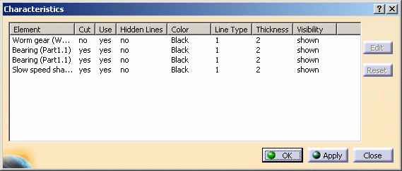
Another way to hide and/or modify part properties in drafting without affecting its links is to right click on the display view frame and click on Overload Properties. This window should appear:

dbcharacteristics01NLS.gif

More about this can be found here.

Hope this helps,
Best of luck!

CATIA V5R19 – user & trainer
ANSYS – beginner
 
Travis,

Was the drawing loaded in the session during the recreation and deletion of the scenes?

To modify the scenes and rename them, the drawing should not be loaded. Sorry that wasn't mentioned in the original statement.
 
Status
Not open for further replies.
Back
Top