I've been thinking about this some more & I was inclined to challenge the applicability (or at least the way its described creates some doubt about what restraints are required) ...
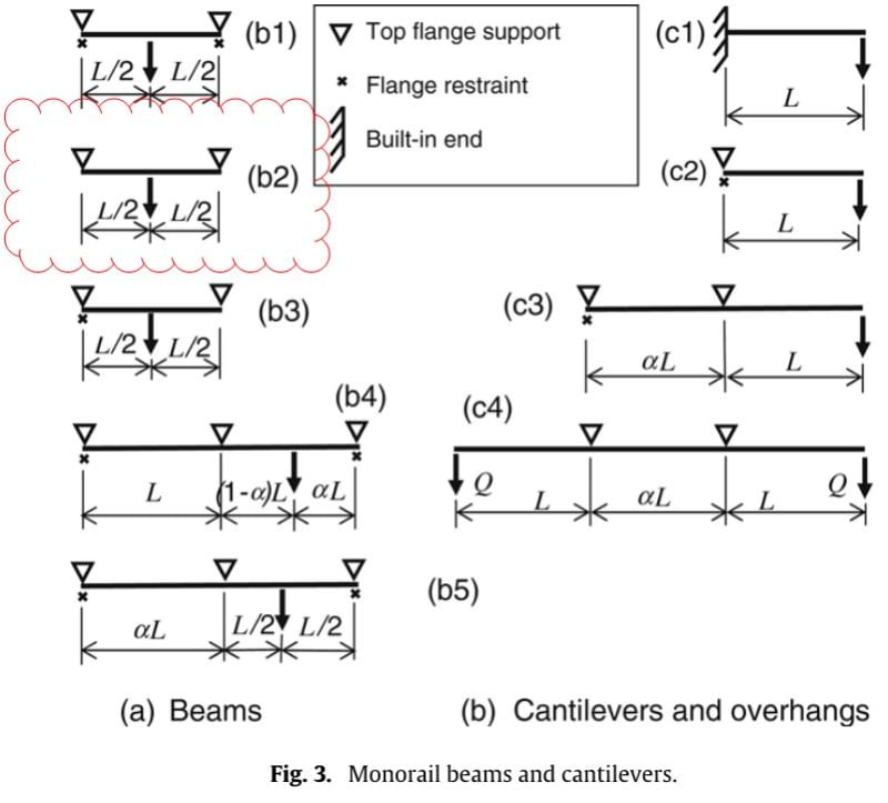
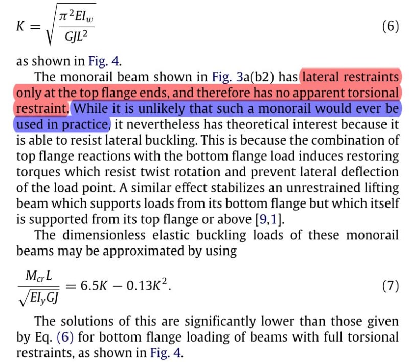
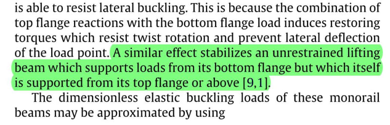
One reason for doubt was the paper is saying you need a lateral restraint at the top flange level (the red highlighted text in Ingenuity's first post) for the approach to be valid. The example details given all seem to imply this (like Figure 1 in the paper). The rod hanger does not prevent the lateral deflection of the top flange as per the logic I was originally assuming, so the procedure might not be directly applicable. The particular scenario being discussed with the hanger is more like the 'similar' lifting beam example given, than maybe the scenario looked at specifically within the paper. The discussed beam is unrestrained at the supports (has vertical support, but not lateral or twist restraints). Paper notes restraints being required, so I decided to check with some numbers to satisfy myself about what is going on.
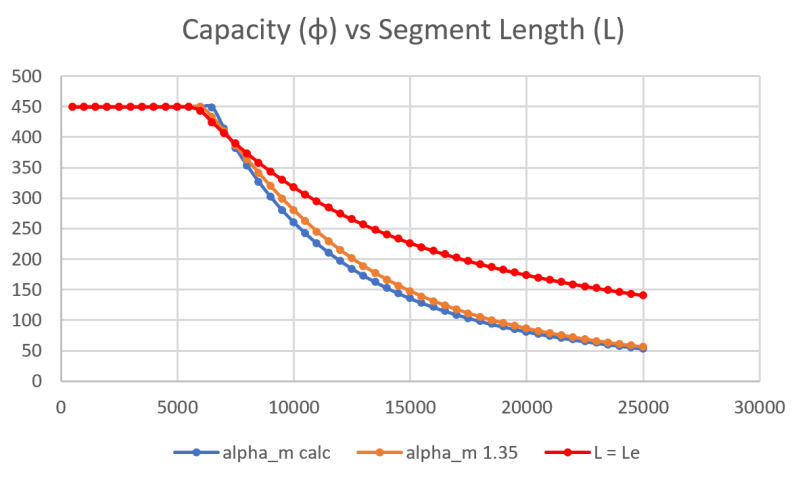
Check the attached example excel calculation, you can clearly see a significant reduction in the capacity (or a corresponding increase in the effective length for buckling) when compared to simply taking L_e = L and directly applying the code checks without the papers buckling analysis. You'd take the approach of L=L_e if you were designing this normally with rotational restraint at one/both ends. So this seems to clarify things (as you would naturally expect a lesser capacity if unrestrained at the ends like the lifting beam analogy), maybe its all poorly phrased in the paper to cause maximum confusion in my brain.
While I believe the alpha_m value is directly equivalent to C_b (albeit with different approximate equations), there are other reductions subsequently being applied to arrive at a capacity for your given system. Alpha_m is further reduced as noted in the paper, refer to equation 18 in the paper as this embodies the further reduction without specifically calling it the alpha_s reduction like in the code.
You should use these further reductions to get the M_bx capacity (which is further reduced by a strength reduction factor of 0.9). AISC probably has other similar reductions to be applied, Mcr is the elastic buckling moment, but not the final capacity. The question you really should be asking if you were to directly apply the code equations would be 'what effective length do the supports/restraints afford the beam', determining the C_b factor isn't really the question you need to directly answer, its embodied in the papers solution even if its not stated in terms of length, but rather buckling moment. If you were to use the 1.35 C_b factor and just follow the code you are not working it out correctly, further information is required to arrive at the actual capacity (see below).
What you can take away from it is that the normal alpha_m from AS4100/NZS3404 for a point load centrally on a beam is tabulated as 1.35, therefore what you are finding is that you simply end up with the typical value which is to be expected, i.e there is no effect of restraints/support/member geometry. Therefore if you are satisfied that its applicable in terms of whether a lateral restraint is required or not, you could simply take the normal Cb factor for the moment diagram shape from AISC, I'm assuming it would also be 1.35 also? I'd note that the paper & code does allow you to sharpen your pencil on the alpha_m value as well, by using the approach noted in equation 19 (alpha_m= Mcrs/Myz), I'm sure AISC would also allow you to work out C_b based on an elastic critical buckling moment analysis as well (I did look but its all a bit foreign to me).
The reality is the C_b or alpha_m factor is in simplistic terms more dependent on the shape of the moment diagram, and not based so much on the restraints, beam length, or what the effective length is, etc. So the alpha_m factor should be the same irrespective of how a simply supported member is restrained, same moment diagram shape = same factor for the same beam.
Its the rest of the working that factors these other things in by effectively working out an effective length over which buckling occurs based on the given support/restraint arrangement. So I propose that C_b is in effect somewhat irrelevant to the problem, what is more relevant is the restraints you have and determination of the effective length to be used. This is the important bit, and the rest of the calculations need to be followed to account for this fact. Simply applying C_b and using the exact length of the beam is possibly not accounting for the correct effective buckling length (see example problem attached, depending on the length of the beam it can grossly overestimate the capacity).
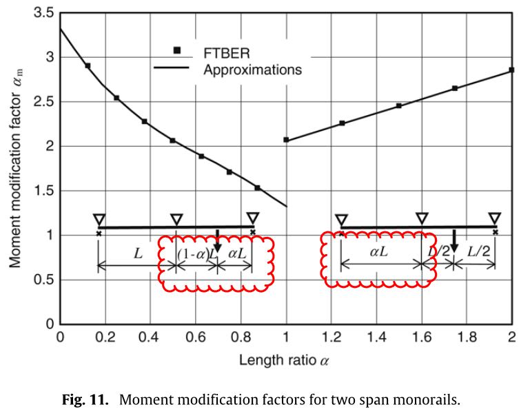
Based on the attached example the statement that the values of alpha_m increases with increasing K seems to be true when worked out using equation 19, but at longer beam lengths alpha_m does dip well below 1.35. This might just be an artifact of the approximation used in equation 7, I'm not really sure. The decrease/increase kind of comes out in the wash resulting in a very small increase in moment capacity (less than 5%) over using the calculated value.
Moral of the story, C_b is based for the most part on the moment diagram shape irrespective of what else is going on, and the solution needs to correctly account for the effective length using the critical buckling analysis approach (accounts for the effects that are restraining buckling).. don't forget about this second part as it is crucial to calculating the correct capacity.