Is a crane rail beam that is supported at each end by hanger connections that attach only to the top flange of the beam considered to be braced for the purposes of the calculation of the lateral-torsional buckling modification factor, Cb? With these end conditions, can you use AISC 14th Eq.(F1-1) to calculate Cb using the length between hangers as the beam length to calculate the moment values?
Navigation
Install the app
How to install the app on iOS
Follow along with the video below to see how to install our site as a web app on your home screen.
Note: This feature may not be available in some browsers.
More options
Style variation
-
Congratulations TugboatEng on being selected by the Eng-Tips community for having the most helpful posts in the forums last week. Way to Go!
You are using an out of date browser. It may not display this or other websites correctly.
You should upgrade or use an alternative browser.
You should upgrade or use an alternative browser.
Cb value for crane rail beam simply supported by hangers attached to top flange only 4
- Thread starter AKM30
- Start date
- Status
- Not open for further replies.
Depends on the connection and how much torsional stiffness, and lateral bracing it affords to the beam.
Presumably the detail has to also transfer crane forces so would have sufficient stiffness? Provide details of the connections and hanger details?
Presumably the detail has to also transfer crane forces so would have sufficient stiffness? Provide details of the connections and hanger details?
- Thread starter
- #3
The crane rail beam is existing and there are no plans available. See attached Photo of the hanger connection for reference. The task is to evaluate the crane rail beam for another load in addition to the rated hoist capacity. I have determined the flexural capacity of the crane rail beam based on measured dimensions according to Section F4 of the AISC specification. The Cb value used will determine whether or not the lateral-torsional buckling limit state will control.
- Thread starter
- #5
The adjacent crane rail beam (connected by hoist bridge beam) has diagonal bracing from the top flange of the crane rail beam up to bottom chord of the roof truss. See attached Photo for reference. Supports are at 24' o.c.
Still don't think there is any lateral restraint to the hanger side, usually a code defines a valid lateral restraint for flexure as preventing either lateral deflection or rotation, or both lateral and rotation of the critical compression flange.
The fact that the crane hoist holds the tension flange (for a series of simply supported spans) does not qualify as a lateral restraint. If the hoist prevents twist of the cross section, perhaps, but for wheels on the top of the bottom flange I find it hard to imagine it restrains the rotation effectively.
Obviously the height of the load being applied below the shear center helps for stability, so make sure you are factoring that into it however your code allows for this fact.
-
1
- #8
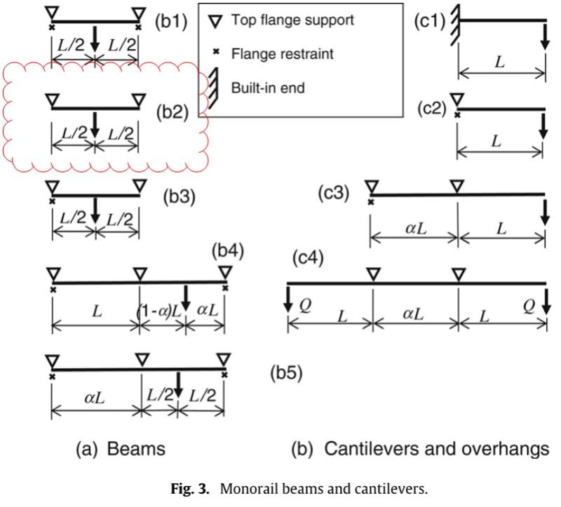
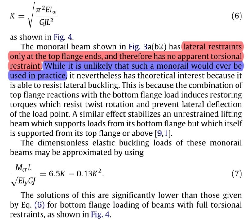
Trahair addresses such a monorail beam restraint condition (or lack-of!!) in his 2008 paper "Lateral Buckling of Monorail Beams": Link

And arrives at an elastic buckling load for condition (b2) of:

To design by buckling analysis, your need to reduce your critical buckling moment to a design/nominal moment resistance, via your code (AU and EC codes require/permit a buckling analysis, not sure about AISC).

And arrives at an elastic buckling load for condition (b2) of:

To design by buckling analysis, your need to reduce your critical buckling moment to a design/nominal moment resistance, via your code (AU and EC codes require/permit a buckling analysis, not sure about AISC).
Edit:- actually re reading the paper I think I misunderstood. So ignore the above comment. Sort of a similar concept to a spreader beam for lifting, finds a state of equilibrium.
Devil's Agent said:Sort of a similar concept to a spreader beam for lifting, finds a state of equilibrium.
Yes, and Trahair states such in the body of his paper:

And via reference to Dux and Kitipornchai's 1990 paper: Link

Yeah, I took that to mean similar but not the same, and incorrectly interpreted 'support = lateral restraint' (and it was all going downhill for me after that!), meaning I interpreted his solutions required a lateral restraint but no twist restraint being required like noted at the beginning of section 4.1 (missed the little crosses they have to distinguish lateral restraints from supports on the graphics). Support and lateral restraint are two different things in the context of what is written.
Thanks for the second link, very handy for justifying lifting beam design.
I agree that this method would nicely cover your query AKM30. Interested to see if it works though as the paper does note that the buckling strength is a lot lower, and it sounded like you were angling for the best possible Cb value to get it to work?
Alpha_m in the paper (from NZ/AU codes) is equivalent to Cb.
- Thread starter
- #12
Agent666, you are correct that I am trying to obtain the best possible Cb value in order to increase my available strength. Currently, I am unable to access the papers from the links above. What is the equation given that references alpha_m? Also, I am not sure how the k value from Eq. 7 of Ingenuity's post relates to the Cb value?
-
1
- #13
K is the Euler effective length buckling factor (eqn 6 in Ingenuity's post). Once you know K, you can work out M_cr using eqn 7. This is the moment that your beam will initiate flexural torsional buckling failure at. M_cr indirectly already includes C_b if I'm not mistaken.
Consider it like this, C_b is a scale factor by which you can factor up the capacity of your given arrangement, when compared to a beam with equal moment being applied that initiates flexural torsional buckling (the case defined as the benchmark for C_b=1.0).
So you can find out C_b by doing the following:-
Work out C_b by taking the ratio of M_cr worked out above and the max moment (M) achieved (i.e. flexural torsional buckling capacity) for the same length simply supported member with equal and opposite moments applied at each end for a constant moment diagram (i.e. the Cb=1.0 definition condition, see your code for this).
i.e.
M_cr (C_b=?)
--------------- = C_b for your given arrangement.
M (C_b=1)
Usually you are coming at it from the opposite direction, knowing C_b based on your moment distribution, and the buckling capacity for a given length beam with Cb = 1, you end up with M_cr = M * C_b (using the authors nomenclature). Above equation is this equation rearranged.
You are getting to M_cr directly using the approach in the paper, but check Cb to make sure it seems logical and within normal bounds. I'm not sure how bad it will be, but would be interested to hear!
Alpha_m is simply noted in other parts of the paper.
If it was not sufficient, I'd look at putting some struts across at top flange level to the adjacent rail, then both beams are effectively braced in the same manner. Hopefully crane clearances might allow this.
-
1
- #14
AKM30 said:Currently, I am unable to access the papers from the links above.
The paper I reference by Trahair is downloaded by payment only, BUT, the University of Sydney Research Report R883 by Trahair, is near-identical to the Engineering Structures paper, freely available from U of S, and I have attached it here.
K will get you the critical elastic buckling moment, Mcr, then calc αm - is a moment modification factor which allows for the non-uniform distribution of bending moment along the beam (similar to AISC Cb factor, as per that Agent666 stated), to arrive at your nominal resistance moment capacity.
There is simple worked example in the attached file.
Enjoy!
- Thread starter
- #15
In regards to my original question regarding Cb, does it simplify to alpha_m = Cb = 1.35 for a configuration as shown Figure 3a.b2? That is my interpretation based on Equation 21a on page 9 from Ingenuity's referenced University of Sydney Research Report R883 by Trahair.
canwesteng
Structural
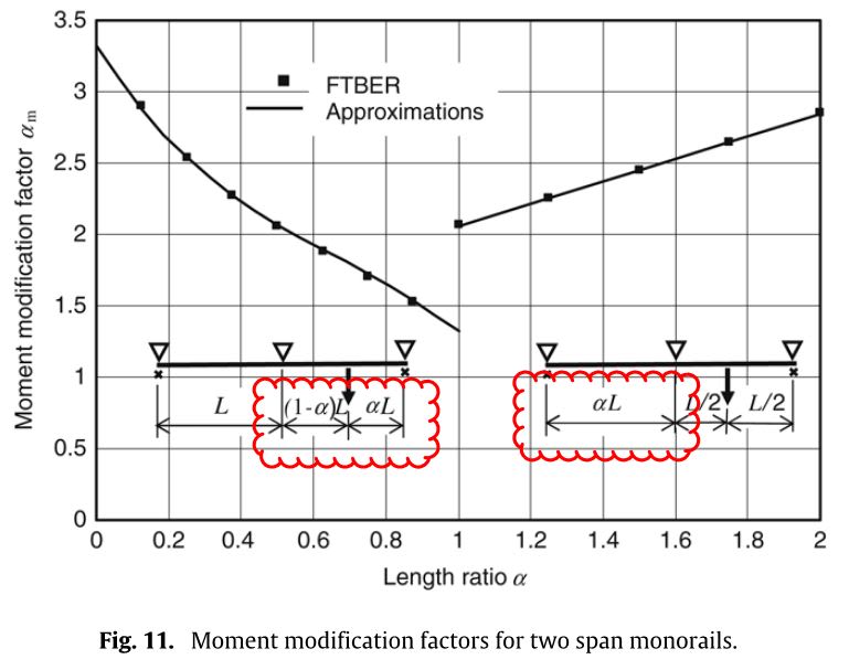
Ingenuity - great paper, but the concept of length ratio is ill defined. Could you shed some light on this? It appears to be either the ratio of the length of the adjacent span to the loaded span, or a parameter to identify where the wheel loads are on the monorail.
-
1
- #17
canwesteng said:...but the concept of length ratio is ill defined. Could you shed some light on this? It appears to be either the ratio of the length of the adjacent span to the loaded span, or a parameter to identify where the wheel loads are on the monorail.
canwesteng: Yes, Trahair got a bit sneaky and used 'α' (length ratio) to describe two related, but differing, lengths.
He used 'α' in single spans with overhangs to cater for a varying internal span, and similarly, for 2-span conditions to cater for differing span lengths. BUT he also mischievously used 'α' to cater for load position in the 2-span condition (with equal spans), as per the following:

I hope that is what your refer.
canwesteng
Structural
That was more or less my interpretation as well - the paper would have been better served with an actual explanation of the variable in each section to clear this up.
I've been thinking about this some more & I was inclined to challenge the applicability (or at least the way its described creates some doubt about what restraints are required) ...
One reason for doubt was the paper is saying you need a lateral restraint at the top flange level (the red highlighted text in Ingenuity's first post) for the approach to be valid. The example details given all seem to imply this (like Figure 1 in the paper). The rod hanger does not prevent the lateral deflection of the top flange as per the logic I was originally assuming, so the procedure might not be directly applicable. The particular scenario being discussed with the hanger is more like the 'similar' lifting beam example given, than maybe the scenario looked at specifically within the paper. The discussed beam is unrestrained at the supports (has vertical support, but not lateral or twist restraints). Paper notes restraints being required, so I decided to check with some numbers to satisfy myself about what is going on.
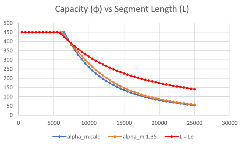
Check the attached example excel calculation, you can clearly see a significant reduction in the capacity (or a corresponding increase in the effective length for buckling) when compared to simply taking L_e = L and directly applying the code checks without the papers buckling analysis. You'd take the approach of L=L_e if you were designing this normally with rotational restraint at one/both ends. So this seems to clarify things (as you would naturally expect a lesser capacity if unrestrained at the ends like the lifting beam analogy), maybe its all poorly phrased in the paper to cause maximum confusion in my brain.
While I believe the alpha_m value is directly equivalent to C_b (albeit with different approximate equations), there are other reductions subsequently being applied to arrive at a capacity for your given system. Alpha_m is further reduced as noted in the paper, refer to equation 18 in the paper as this embodies the further reduction without specifically calling it the alpha_s reduction like in the code.
You should use these further reductions to get the M_bx capacity (which is further reduced by a strength reduction factor of 0.9). AISC probably has other similar reductions to be applied, Mcr is the elastic buckling moment, but not the final capacity. The question you really should be asking if you were to directly apply the code equations would be 'what effective length do the supports/restraints afford the beam', determining the C_b factor isn't really the question you need to directly answer, its embodied in the papers solution even if its not stated in terms of length, but rather buckling moment. If you were to use the 1.35 C_b factor and just follow the code you are not working it out correctly, further information is required to arrive at the actual capacity (see below).
What you can take away from it is that the normal alpha_m from AS4100/NZS3404 for a point load centrally on a beam is tabulated as 1.35, therefore what you are finding is that you simply end up with the typical value which is to be expected, i.e there is no effect of restraints/support/member geometry. Therefore if you are satisfied that its applicable in terms of whether a lateral restraint is required or not, you could simply take the normal Cb factor for the moment diagram shape from AISC, I'm assuming it would also be 1.35 also? I'd note that the paper & code does allow you to sharpen your pencil on the alpha_m value as well, by using the approach noted in equation 19 (alpha_m= Mcrs/Myz), I'm sure AISC would also allow you to work out C_b based on an elastic critical buckling moment analysis as well (I did look but its all a bit foreign to me).
The reality is the C_b or alpha_m factor is in simplistic terms more dependent on the shape of the moment diagram, and not based so much on the restraints, beam length, or what the effective length is, etc. So the alpha_m factor should be the same irrespective of how a simply supported member is restrained, same moment diagram shape = same factor for the same beam.
Its the rest of the working that factors these other things in by effectively working out an effective length over which buckling occurs based on the given support/restraint arrangement. So I propose that C_b is in effect somewhat irrelevant to the problem, what is more relevant is the restraints you have and determination of the effective length to be used. This is the important bit, and the rest of the calculations need to be followed to account for this fact. Simply applying C_b and using the exact length of the beam is possibly not accounting for the correct effective buckling length (see example problem attached, depending on the length of the beam it can grossly overestimate the capacity).
Based on the attached example the statement that the values of alpha_m increases with increasing K seems to be true when worked out using equation 19, but at longer beam lengths alpha_m does dip well below 1.35. This might just be an artifact of the approximation used in equation 7, I'm not really sure. The decrease/increase kind of comes out in the wash resulting in a very small increase in moment capacity (less than 5%) over using the calculated value.
Moral of the story, C_b is based for the most part on the moment diagram shape irrespective of what else is going on, and the solution needs to correctly account for the effective length using the critical buckling analysis approach (accounts for the effects that are restraining buckling).. don't forget about this second part as it is crucial to calculating the correct capacity.
- Status
- Not open for further replies.
Similar threads
- Replies
- 21
- Views
- 5K
- Replies
- 7
- Views
- 3K
- Locked
- Question
- Replies
- 2
- Views
- 742
- Locked
- Question
- Replies
- 2
- Views
- 881

