Eng-Tips is the largest engineering community on the Internet

Intelligent Work Forums for Engineering Professionals

Centrifugal pumps running in parallel, one pump with high vibration

Status
Not open for further replies.

Mike9208

Mechanical
Feb 23, 2023
12
0
0
HK
Hi to all colleagues out there,

In the ethylene plant that company where I work is biulding there are three ITT Goulds Non-API pumps OH1, namely P-1234A/B/C, running with equalized water, rated capacity each one 300m3/h@40.3m.

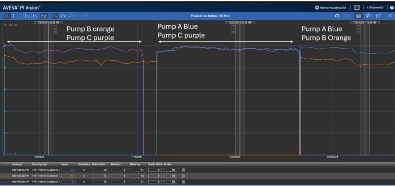
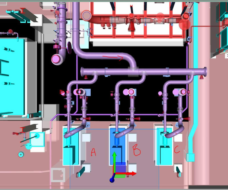
There are several operating cases, but the normal one requires two pumps running in parallel. When we run pump A and B, the pump B is having a higher vibration than A. When runs B and C, again B has higher vibration than C. Last case is when A and C runs in parallel both has similar vibration and under normal ISO limits for newly commisioning machines. in the physical arrangement the pump B is in the middle, and suction piping layout is not symetrical. I have attached a snapshot of the 3D. Vibration measurements found 4X component. Also, found sort of cyclic sound coming from the piping. Current absorption of pump motor B is lower than other two motors.

my first thought is that 4X is coming from vane pass frequency due to operation too much to the left of BEP which is somehow confirmed by current absoption being less than other pumps. However I dont have any explanation of why this happens only with one pump. someone suggested the problem comes from the suction piping layout.

Any ideas of why only one pump is having this behaviour and any suggestions of how to solve? Client wants to rotate the two pumps in operation to have "uniform" wear in all the three pumps so now I need to find a way to reduce vibration of pump B.

Appreciate any support.

P-5655Layout_vdh9io.jpg

P-5655B_Vibration_pvypef.jpg
 
Replies continue below

Recommended for you

Pump curves with actual operating performance/s of the individual pumps under the various conditions plotted for each unit might throw a bit of light onto the problem.

It is a capital mistake to theorise before one has data. Insensibly one begins to twist facts to suit theories, instead of theories to suit facts. (Sherlock Holmes - A Scandal in Bohemia.)
 
Pipe sizes?

--Einstein gave the same test to students every year. When asked why he would do something like that, "Because the answers had changed."
 
Thanks for the replies,

1- Suction common header is 18" and pipe enters in 10" in each pump, discharge goes 10" from each pump and increase to 18"
2- One of the strange things is that the PG at discharge of pump B fluctuates from 4.2kg/cm to 4.5kg/cm2, while pump A or C is stable in 4.5. I will try to run the pumps and get again the discharge pressure at plot into the curves.

Additional info: pump B was open some time ago due to high vibration and found corrosion inside as shown in the attachment.


 https://files.engineering.com/getfile.aspx?folder=3c18001f-44a8-4ae3-9379-631136290e37&file=P-5655_inside.png
The picture looks like cavitation. Edit: based on additional information Without any vibrational information, my first thought is NPSH / cavitation issues. Someone mentioned the pump curves, which initially, I think would be helpful.
Have you ruled out NPSH or air entrainment issues? What do the suction pressure look like?
What flow control methods are being used? VFDs? Spillbacks?

rated capacity each one 300m3/h@40.3m.
So, 2 pumps running - 600m3/h. Is that what the system is designed for?
Let me provide a scenario of what I have seen could have happened.
Original design: min flow - 300m3/h max flow - 400m3/h / original pump spec - 3 pumps rated at 200m3/h with 2 running in parallel. Pipe design - 400m3/h.
Then somewhere in the detailed design process, someone has a "great" idea. "Since min flow is required 90% of the time, let's get 300m3/h pumps, then only one pump needs to be running to supply min flow." or pump vendor says "Hey, I can sell you these 300m3/h pumps for less than I can 200m3/h pumps"

Without further information, I have no idea if the scenario I provided is relative or not, but I am providing it as food for thought, that unless you know the background of how's and why's the current design came to be, it might be worth getting some more background information.

 
I feel like I need glasses when I try to read those plots (better graphical resolution would help!)

I'm also lacking enough imagination to understand the physical layout shown... is that top view or side view? Are these vertical or horizontal pumps.

If the system flow resistance is steady, maybe you can compare configurations AB/AC to AC... the latter would have highest flow and discharge pressure if B is the weakest pump for whatever reason (yes I realize that whatever reason is what you're probably trying to figure out)

The vibration reading on the pipe may or may not be significant... is it the same frequency as on the pump? Does it exist in similar magnitude on the pipes for the other pumps?

Seems like you confirmed by bump test there was a natural frequency at the same frequency as the high vibration near 100hz? Was that in one or both radial directions? Was the measured vibration while running directional? Did the other pumps have similar natural frequency?
 
Describe "equalised water" pls - is this stream to these pumps solids laden ? Any volatile components in this stream ? Suction strainer all clear on B pump?
Since you have low current on B pump, that perhaps excludes mechanical issues with a gearbox as root cause. Is there a gearbox here ?

 
Heavyside1925:
Looks more like corrosion erosion than cavitation, to the point I would say it's not cavitation.
A few photos of the impeller would be of interest.

It is a capital mistake to theorise before one has data. Insensibly one begins to twist facts to suit theories, instead of theories to suit facts. (Sherlock Holmes - A Scandal in Bohemia.)
 
thanks for valuable comments.
The view I posted orginally is top view, these three pumps are horizontal OH1 type. Pumps runs with motor without VFD, and without gearbox.
I will send in attachment the PID arrangement, pump curves (from performance test) and vibration report.

In our opinion is not cavitation, but running time of pump B is the less among the three pumps, so erosion could be but definetly not the cause of vibration. Also, we understand that vibration spectrum of cavitation is very charasteristic and we dont see it here in any of the pumps.

P-5655A: 6200 hrs
P-5655B: 2000 hrs
P-5655C: 2600 hrs


It is still unclear why when pump B runs alone the vibration dissapears, but when runs in parallel with either A or C vibration appears and absorbed current of motor B gets lower in comparison when runs alone.

I am still waiting to get more data from Operations team. Has anyone had experience of suction piping layout casuing more flow going to one pump (say A in my case) and less flow goping to other one (pump B) when running in parallel?
 
 https://files.engineering.com/getfile.aspx?folder=2a7db7d7-4240-4345-9989-ad4a237378bb&file=Pages_from_P&ID_Master_17_May_2022.pdf
Performance curve and trend for current. When pump B runs in parallel with other pump absorbs 41-42Amp, while other two pumps are stable at 48Amp

trend_zq03mc.jpg
 
Georgeverghese (Chemical), we dont have suction strainer in these pumps, the eq water is Oily Water/ Domestic Wastewater with Total suspended solids of 2400ppm (0.240wt% solid)
 
So these are fixed speed pumps. Can we see PID which shows individual min flow controls and overall capacity control ?
If there is no suction strainer on these pumps, could there be some additional erosion or wear on the impellers on the B pump that has increased its NPSHr ?
Line velocity at 600m3/hr on the DN450 line is 1m/sec, at 300m3/hr on the individual DN250 feeder is 1.7m/sec and pressure drop /100m is low in both cases -looks okay to me.
You say there is oily water here in this pit. Presume this stream is not oily water surface runoff from process areas so oil content would be very low normally ?? Why would flow demand be so large as 600m3/hr otherwise ? If oily water content is anything more, then NPSHa should have based on the vapor pressure of the oily component and not on water vapor pressure. Also, what is the suction lift elevation from the pit normal or min level going to pump centre line ?

 
Hi,
What were the initial vibrations' level at the start-up of the project (base line) for the 3 pumps?
Are those pumps identical? Please share the pumps curves.
Did you check the suction lines of the pumps and the pump impellers?
Did you check the foundation?
Any issues with alignment?
Can you share a PID/Isometric of the 3 pumps?
My 2 cents
Pierre
 
The only thing I can see which might be worth looking at is whether the inlet to pump B is too close to the incoming line creating excess swirl or other flow disturbance.

You could change the suction pipework or introduce a flow plate in the 10" line?

But pump B is operating at 15% less power which equates to about 200m3.

Can you get flow data for each pump in operation? Or do a test on pump b alone to check the pump curve?

Also what temperature is this running at? Could the header be expanding or contracting and putting forces on the inlet line to pump B that it doesn't see when its running on its own? Doesn't really explain the lower flow, but might the vibration. Maybe there are two issues at play here (vibration and performance) that are not directly connected?

Remember - More details = better answers
Also: If you get a response it's polite to respond to it.
 
Hi all,
Looking at the 3D image (plan view), it would appear that the 10" takeoff's from the 18" header, come off on the (18" horizontal) centerline?
Why the suction lines were designed with 2 x 90 deg bends, is not evident.
The reducers before the pump. Are they concentric or eccentric?
Reason for the above questions, there is a good change of vapour sitting in the high points (18" header) and the 10" line before the reducer. Coupled with the "closeness" of the B pump takeoff from the incoming junction/feed pipe. These multiple change of directions will create turbulent flows and all gas's will rise to the high points and throttle flow. This shows in terms of vibration in pump B. Put a stethoscope onto the pump casing and listen for the crackling sound. (A screwdriver against your ear will work just as good). The next thing will e the failure of the pump shaft, right behind the impeller. Due to cyclic fatigue.
 
I think the first step is to determine if it's a mechanical issue, piping issue or process issue.
As far as mechanical issue, is it possible to swap pumps and see if the issue follows? My thinking goes as follows. The maintenance folks seem to know what they are doing and considering they have worked on/rebuilt all three pumps and the only pump to continue to have issues is B pump, which lends me to suspect some sort of defect in a pump component outside of normal rebuild and tolerance checks. Other than putting a new pump in its place, I would consider swapping and see if the issue follows.
As far as piping. Based on the plan view snapshot you shared, I would consider the forces at the 18" tee into the 18" manifold and the moment is causes around the supports on the 18" manifold. This would indicate that when the 10" suction for B is in compression, the suctions of A and C would be in tension and vise vera. The forces on B pump suction nozzle could be much higher than A and C. If piping stress has not been thoroughly modeled and considered, there could be issues that may require pipe and support rework. If a flexible spool could be installed on pump B suction to decouple it from the piping, this could aid in diagnosing the issue.
As far as process. I think both georgeverghese and Nutzman bring up very valid considerations concerning entrain air and oily water NPSH. I especially like Nutzman's screwdriver of the pipe idea. Another option would be a sight glass to actually see the condition of the fluid on the suction side.
 
Think it was a bad idea to remove suction strainers on these pumps. Most of the erosive sediment probably goes into the B pump, given its proximity to the 18inch feeder. May be better if Y type strainers were to be replaced with higher dirt holding capacity basket strainers if space allows. If this goes on for much longer, A and C pumps may suffer the same fate.
There is an integral pressure balance line on these larger pumps that reduces the loading on the thrust bearings - is this line bunged up with solids ? How are the shaft seals holding up in this operation ? - with fouling process fluid used as sealing medium.
Is there a foot valve in the equalisation pit suction line- when was this last checked ?
 
I think you could dismiss the suction pipe work as being the cause as there is certainly enough straight run of pipe after any bends etc leading to the pump inlets to ensure flow into the 3 units is ideal, the only other concern could be some form of pre-rotation - however this would be a long shot as A & C running together seem ok as does B running alone.

For me, it's interesting that for 3 standard production pumps supposedly tested are returning nearly exactly the same hydraulic results - that is virtually impossible - the very reason as to why pump test standards have a tolerance on any guaranteed performance duty point.

The pumps need performance testing in-situ:
1 operating individually
2 A + B
3 A + C
4 B + C

The discharge pipework should also be looked into for induced vibration under certain conditions, again a long shot - but!

It is a capital mistake to theorise before one has data. Insensibly one begins to twist facts to suit theories, instead of theories to suit facts. (Sherlock Holmes - A Scandal in Bohemia.)
 
Hi Mike9208,
The 3D shows 2 items in the pump suction lines. One appears to be a butterfly valve and the other appears to be a spacer. Could it be that the "B" butterfly valve does not fully open or that a wrong spacer with smaller bore is installed?
 
Status
Not open for further replies.
Back
Top