Continue to Site

Eng-Tips is the largest engineering community on the Internet

Intelligent Work Forums for Engineering Professionals

  • Congratulations cowski on being selected by the Eng-Tips community for having the most helpful posts in the forums last week. Way to Go!

CFM Deck Support Thing at Metal Deck Direction Change 3

Status
Not open for further replies.

KootK

Structural
Oct 16, 2001
18,572
You know how, at a deck direction change, you need HSS or something on your steel beams between joists to pick up the deck not parallel to the beam? I'm missing some of those and am in danger of having to pay for them instead of Christmas this year. Is there any kind of CFM member that could be used for this purpose instead of HSS/angles that would be cheap? The loads are nothing of course.

I'm going to violate KootK policy and not supply a sketch here. I'm too busy so, instead, I'm just going to draw upon previously earned good will. Besides, if you don't understand what I've written, you've probably got no business responding anyhow.

I like to debate structural engineering theory -- a lot. If I challenge you on something, know that I'm doing so because I respect your opinion enough to either change it or adopt it.
 
Replies continue below

Recommended for you

Do you have a sketch? Is framing OWSJ or steel beams? Can you use a CFS 'screed angle'? The member at the transition in deck span may be located at the U/S of the deck and the deck is puddle welded to it. Deck spanning at right angles should be puddle welded to the same member. The deck should have foam 'fillers' to keep the concrete from 'flowing out'. How did the contractor intend to construct this? and were there any shop drawings?

Dik
 
-OWSJ
-Steel Beams
-No screed angle as the slab keeps on trucking past this.
-Depth = 2.5"
-Don't sweat contractors and shop drawings. I own this.

I like to debate structural engineering theory -- a lot. If I challenge you on something, know that I'm doing so because I respect your opinion enough to either change it or adopt it.
 
I assume he's talking 4" deep for a standard joist seat type idea.

I don't see why you couldn't put a 4" deep light gauge channel. Are you relying on that area to do any diaphragm load transfer action or is it just along for the ride?
 
- Diaphragm irrelevant
- 2.5" joist seats. It's US; 4" is a CANAM thing.

I like to debate structural engineering theory -- a lot. If I challenge you on something, know that I'm doing so because I respect your opinion enough to either change it or adopt it.
 
If I understand the situation correctly.....I've used Z/C sections for this purpose in the past.
 
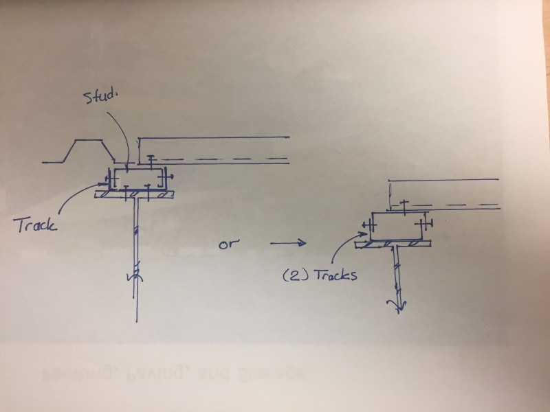
Kootk, see picture below. This might work for you. If you can get studs 2.5" wide that would be ideal. If not you can use two tracks and adjust the height as needed and screw the flanges together.
deck_fkmwbp.jpg
 
If you really want to skimp just throw in some wood blocking.
 
There it i! Great solution. Imagine those sketches with HSS instead of the CFM and you've got the sketches I should have posted in the first place.

I like to debate structural engineering theory -- a lot. If I challenge you on something, know that I'm doing so because I respect your opinion enough to either change it or adopt it.
 
1. Can the joist supplier get you some quick 2.5K's?
2. Use two - 2 1/2" deep light gage "C" joists back to back between joists - then screw them together with a couple of #10 screws and screw down to the supporting beam.
3. Use (2) 2x4's ripped down to 2 1/2" depth from 3 1/2 and glue down to the beam. (I know - weird)
4. Use a light gage "Z" shape to lap over the supporting deck end, drop vertically between the two deck ends and then lap under the supported deck side flange. Screw together aggressively.


Check out Eng-Tips Forum's Policies here:
faq731-376
 
Glad I asked now. So many options.

@JAE/DETstr: fire an issue for the wood option? This one's non-combustible in general.

I like to debate structural engineering theory -- a lot. If I challenge you on something, know that I'm doing so because I respect your opinion enough to either change it or adopt it.
 
Fire treated lumber?

Check out Eng-Tips Forum's Policies here:
faq731-376
 
Got it. Thanks all. Friends in need. I'm a satisfied distressed damsel.

I like to debate structural engineering theory -- a lot. If I challenge you on something, know that I'm doing so because I respect your opinion enough to either change it or adopt it.
 
[blue](JAE)[/blue]

4. Use a light gage "Z" shape to lap over the supporting deck end, drop vertically between the two deck ends and then lap under the supported deck side flange. Screw together aggressively

JAE, anyway you could provide a quick sketch of this? I use to use a Z-Shape for this myself.....but what I did was cut off one leg.....screw it/puddle weld down to the supporting beam.....then lap it a little off center (on one side) of the beam. You may have shown me a [better] alternative way here.

 
Thanks dik. What I was talking about was the member rotated 90o. But this is a good idea.
 
Used this detail lots of times... need foam blockouts to keep the concrete from flowing through.

Dik
 
@dik: I considered that and mostly like it. The problem that I have is that, when I look at the realities in plan, that angle would never terminate over a joist. It would always have to cantilever up against a column or something. How do you deal with that? Design the cantilever? Maybe I could mix and match and use lugs where the cantilever would otherwise be.


I like to debate structural engineering theory -- a lot. If I challenge you on something, know that I'm doing so because I respect your opinion enough to either change it or adopt it.
 
Not usually a problem... you require some angle framing at columns to accommodate interrupted deck.

From my project notes (Modify as required):

STRUCTURAL STEEL (OWSJ AND LONG SPAN TRUSSES)

OWSJ AND LONG SPAN TRUSSES SHALL CONFORM TO THE REQUIREMENTS FOR STRUCTURAL STEEL U/N

OWSJ SHALL BE IN ACCORDANCE WITH THE STEEL JOIST INSTITUTE U/N

OWSJ AND LONG SPAN TRUSSES ARE TO BE DESIGNED FOR ALL LOADS NOTED ON THE DWGS

TOP CHORD MEMBERS SHALL BE DESIGNED FOR A SUPERIMPOSED [250 | 300 | 400 | 500] LB LIVE LOAD LOCATED BETWEEN ANY TWO PANEL POINTS

BOT CHORD MEMBERS SHALL BE DESIGNED FOR A SUPERIMPOSED [100 | 150 | 200] LB LIVE LOAD LOCATED BETWEEN ANY TWO PANEL POINTS

WEB MEMBERS WITHIN THE MIDDLE 1/4 SPAN SHALL BE DESIGNED FOR A MIMIMUM COMPRESSION LOAD EQUAL TO 20% OF THE END REACTION

JOIST SEATS LESS THAN 4" HIGH SHALL BE DESIGNED TO RESIST A 2000 LB LATERAL LOAD APPLIED TO THE TOP OF THE JOIST CHORD U/N

JOIST SEATS LESS 4" HIGH OR GREATER SHALL BE DESIGNED TO RESIST A 1500 LB LATERAL LOAD APPLIED TO THE TOP OF THE JOIST CHORD U/N

OWSJ AND LONG SPAN TRUSSES SHOP DRAWINGS SHALL BEAR THE SEAL OF AN ENGINEER REGISTERED IN THE PROVINCE WHERE THE PROJECT IS LOCATED WHO WILL BE RESPONSIBLE FOR THE DESIGN, FABRICATION AND INSTALLATION OF SAME

OWSJ AND LONG SPAN TRUSSES SHALL NOT BE FIELD MODIFIED WITHOUT WRITTEN PERMISSION FROM THE ENGINEER WHOSE SEAL HAS BEEN AFFIXED TO THE SHOP DRAWING

PROVIDE BRIDGING FOR OWSJ AND LONG SPAN TRUSSES IN ACCORDANCE WITH CSA S16

SECURE OWSJ TO SUPPORTING BEAMS AND COLUMNS WITH 3/16" X 2" FILLET WELDS EA SIDE MIN. REFER TO OWSJ SHOP DRAWINGS FOR FASTENING

SECURE LONG SPAN TRUSSES TO SUPPORTING BEAMS AND COLUMNS WITH 2 - 3/4" DIA A325 BOLTS MIN (SLIP CRITICAL). REFER TO SHOP DRAWINGS FOR FASTENING

COORDINATE HOR BRIDGING WITH MECHANICAL EQUIPMENT TO AVOID CONFLICTS IN PLACEMENT

OWSJ SPACING NOT TO EXCEED DESIGN CAPACITY OF VICWEST W 938, [0.030 | 0.76] ROOF DECK IN AREAS OF SNOW ACCUMULATION

OWSJ SPACING NOT TO EXCEED THAT REQUIRED FOR VICWEST W 938, [0.030 | 0.76] ROOF DECK TO MEET THE LOADING REQUIREMENTS SPECIFIED BY FM GLOBAL

OWSJ SUPPLIER TO PROVIDE FOR SUPPORT OF MECHANICAL EQUIPMENT AND PIPING NOTED IN THE CONTRACT DOCUMENTS

PROVIDE CAMBER TO OWSJ WITH LENGTHS GREATER THAN [30FT | 10.0M]. CAMBER TO BE EQUAL TO DEFLECTION CAUSED BY DL U/N

PROVIDE CAMBER TO LONG SPAN TRUSSES. CAMBER TO BE EQUAL TO DEFLECTION CAUSED BY DL U/N

PROVIDE SUFFICIENT CAMBER AND STIFFNESS TO OWSJ AND LONG SPAN TRUSSES TO PREVENT 'PONDING'

TAKE PRECAUTIONS WHEN PLACING TOPPING SLABS OVER OWSJ TO AVOID LATERAL DEFLECTION OR TWISTING

THE DEPTH OF THE OWSJ SHOE SHALL BE [4" | 100 MM] U/N

THE LENGTH OF THE OWSJ SHOE IN THE DIRECTION PERPENDICULAR TO THE WALL SHALL BE [4 | 100] MIN. THE C/L OF BEARING SHALL BE THE C/L OF WALL U/N

PROVIDE BEARING PLATES FOR OWSJ BEARING ON MASONRY. MAX SERVICE LOAD BEARING STRESS UNDER BEARING PLATES ON MASONRY TO BE [160PSI | 23KPA]

TIE OWSJ BOT CHORD TO COLS U/N. WHERE AN OWSJ DOES NOT 'LINE UP' WITH A COL, PROVIDE A TIE FROM THE OWSJ ON EA SIDE OF THE COL. PROVIDE A STRUT BTN OWSJ AT THE LOCATION OF THE TIE. TIES AND STRUTS TO BE [L3x3x1/4 | L75x75x6] U/N

TJ ON PLAN DENOTES A TIE FROM THE BOT CHORD OF THE OWSJ TO A STEEL BM/COL


STEEL DECK

STEEL DECK SHOP DRAWINGS SHALL BEAR THE SEAL OF AN ENGINEER REGISTERED IN THE PROVINCE WHERE THE PROJECT IS LOCATED WHO WILL BE RESPONSIBLE FOR THE DESIGN, FABRICATION AND INSTALLATION OF SAME

STEEL ROOF DECK SHALL CONFORM TO CSA S136 AND CSSBI-10M 'STANDARD FOR STEEL ROOF DECK'. THE GALV COATING FOR ROOF DECK NOT EXPOSED TO THE WEATHER SHALL CONFORM TO COATING DESIGNATION ZF75, UNLESS NOTED OTHERWISE. COATING FOR STEEL ROOF DECK EXPOSED TO THE ELEMENTS SHALL CONFORM TO COATING DESIGNATION Z275 WITH A BASE STEEL NOMINAL THICKNESS AS SHOWN ON THE DWGS

STEEL FLOOR DECK SHALL CONFORM TO CSA S136 AND CSSBI-12M 'STANDARD FOR COMPOSITE DECK'. FOR INTERIOR APPLICATIONS, IT SHALL HAVE A COATING CONFORMING TO COATING DESIGNATION ZF75. FOR EXTERIOR APPLICATIONS IT SHALL CONFORM TO COATING DESIGNATION Z275 WITH A BASE STEEL NOMINAL THICKNESS AS SHOWN ON THE DWGS

THE PROFILE FOR STEEL FLOOR DECK SHALL CONFORM TO THE REQUIREMENTS FOR USE IN COMPOSITE STEEL BEAM CONSTRUCTION AS OUTLINED IN S16

SHOP DRAWINGS SHOWING LAYOUT OF DECK UNITS, LOCATIONS AND DETAILS OF FASTENING AND OPENINGS TYPE AND GAUGES OF DECK MATERIALS SHALL BE SUBMITTED FOR REVIEW BEFORE FABRICATION COMMENCES

THE USE OF INVERTED DECK PROFILES MUST BE APPROVED BY THE ENGINEER

DECKING SHALL SPAN CONTINUOUSLY OVER THREE OR MORE SUPPORTS

DECK JOINTS SHALL BE STAGGERED. DECK FASTENING SHALL PENETRATE THROUGH A MAXIMUM OF TWO LAYERS OF DECKING

EXCEPT AS NOTED, STEEL DECK SHALL BE FASTENED AS FOLLOWS:
-DECKING SHALL BE WELDED TO SUPPORTING STEEL BY 5/8"%%D WELDS AT ALTERNATE FLUTES (12" MAX)
-END LAPS SHALL BE NOT LESS THAN 4" AND FORMED OVER A SUPPORT
-SIDE LAPS SHALL BE MECHANICALLY FASTENED AT NO MORE THAN 24" CENTRES
-WELDS, ABRASIONS AND FIELD CUT OPENINGS SHALL BE FIELD PAINTED WITH AN APPROVED PRIMER

EXCEPT AS NOTED, STEEL DECK SHALL BE FASTENED AS FOLLOWS:
-DECKING SHALL BE SECURED TO SUPPORTING STEEL BY #12-24x1-1/4 SELF DRILLING AND TAPPING SCREWS AT ALTERNATE FLUTES OR AT 16" MAX O/C
-SIDE LAPS SHALL BE SECURED USING #12-24x3/4 SCREWS AT NO MORE THAN 16" CENTRES

POWDER ACTUATED FASTENERS AND/OR SCREW FASTENERS MAY BE HAVING THE SAME OR GREATER CAPACITY MAY BE USED IN LIEU OF WELDS AND MECHANICAL FASTENERS

POWDER ACTUATED FASTENERS MAY BE USED IN LIEU OF SCREW FASTDERS

PROVIDE METAL DECK ACCESSORIES SUCH AS COVER PLATES, CHANNELS, DECK EXTENSIONS, UPSTANDS, SCREED FLASHINGS, FLUTE CLOSURES, CELL CLOSURES AND EDGE STRIPS AS REQUIRED

PROVIDE [L1-1/2X1-1/2X3/16 | L40x40x5] TEMPORARY SUPPORT ANGLES TO SUPPORT INTERRUPTED DECK AT BEAM-COL CONNECTIONS


Dik
 
Status
Not open for further replies.

Part and Inventory Search

Sponsor