Continue to Site

Eng-Tips is the largest engineering community on the Internet

Intelligent Work Forums for Engineering Professionals

  • Congratulations KootK on being selected by the Eng-Tips community for having the most helpful posts in the forums last week. Way to Go!

Changing structures over time 3

Status
Not open for further replies.

Danielsp

Civil/Environmental
Apr 5, 2018
61
Hello folks

I am a civil Engineer, M.SC. in structures Engineering and I model and design structures, mostly using FEM.

Right now I am interested in static modeling structures that change over time. Some cases are really simple, for instance:

1) If you load a structure then remove some part of it while keeping the same load, then the new moments, shear forces and strains can be easily obtained by simply ignoring the original structure. You load the new structure and that's it.

2) If you apply Load 1 on Structure 1, then add a structural element to it and finally apply a new Load 2, then the final state of forces and displacements is obtained by adding L1 on Structure 1 to L2 on structure 2.

So far, no big deal.
But what if after the first load you add a new part to the structure while loaded and then remove an old one?
 
Replies continue below

Recommended for you

steveh49, I believe you're right and that the principle works also for indeterminate structures. At least for a test situation I calculated by hand, which is this:

Suppose you have n springs of constant K in paralell supporting a load P, then each spreing would take P/n under displacement x0 = P/(Kn).
If you add a new spring while the structure is loaded, no force or displacement will change and the new spring will be under no load.
But after you remove one of the original springs under stress, what will be the total displacement x of the springs?

In the final situation we have n-1 old springs with displacement x and a new one under displacement x-x0. Equilibrium requires that the total spring force is still P, so

(n-1)Kx +K(x-x0) = P
But Kx0 = P/n, so
(n-1)Kx +Kx -P/n = P
nKx = P +P/n
Kx = P/n +P/n² is the new force in each of the old springs, and the new spring has force K(x-x0) = P/n²

Those are exactly the values you'd get if you added
a) original structure (n springs) under load P, that's P/n for old springs and 0 for new (yet to come) spring
b) new structure (also n springs) under load P/n (replacing a removed spring), that's P/n² for old springs and new alike.
 
Danielsp said:
If you add a new spring while the structure is loaded, no force or displacement will change and the new spring will be under no load.
This seems like an academic stretch to me. If you add an exactly similar spring to the arrangement it would take load and reduce the load on the other springs. If however you added a spring with a different neutral depth then perhaps no elongation of that spring. But how does this all relate to a real world structure I think is everyone's question. It really depends on the element/s your considering, the loading, and the support conditions.
 
driftLimiter, general principles might seem like academic stretches, but they are all we have in order to make models.

The fact that you add a spring after the original structure is deformed is indeed equivalent to using a spring with a different neutral depth.

How does this relate to a real world structure?
Well, if you only build stuff then load it... it doesn't. I know that's the vast majority of cases in professional practice and also in theoretical structural analysis, both static and dynamic.
But if you happen to need to demolish a specific part of a structure and wanna make sure the whole thing doesnt come down... you better build a reinforcement somewhere first. Then, it would be nice if you could put some numbers on final displacements, moments, shears and axial forces to make sure the structure can take them.

Also, dik gently provided us with a picture of a real world application of those principles.
 
Danielsp said:
The fact that you add a spring after the original structure is deformed is indeed equivalent to using a spring with a different neutral depth.

I don't think that this is true in general. It might be true in a specific loading or support condition. Lets say your hanging your load P from n springs. You add another identical spring to the arrangement, you must stretch it by the amount of the displacement of the original structure. Then after you stretch it and attach it to the load, the displacement would reduce and the force in each spring would reduce proportionally.

If you want a good answer you will have to be more specific.
 
rb1957, I can rerun the model as much as I want, but simply applying the original load to either the original or the new structures (they can even be identical, apart from locked in stresses!) will not provide the results of the structure in the situation I described. Look at the spring example I used, or the one by steveh49 .
 
Yes, driftLimiter. If I pre-stretched the new spring by just the right amount, then I could just rerun the model.
But that is not the situation I described, which is: you insert a new, unloaded part to an existing, loaded structure and only then you remove something from the original structure.
 
If all the elements remain elastic in all the different loading scenarios, then static equilibrium and displacement compatibility must always be satisfied. If this is satisfied in your modeling then your results will be consistent with reality. Adding certain elements in a displaced condition might change the stiffness distribution in your structure and thus change the load path. You can used a phased construction analysis technique to model the effect of changing elements/Loads in a displaced structure. This is often done for composite concrete construction.
 
steveh49, apparently you nailed it, although I'd still like to create a test case that does not involve adding or removing supports (unfortunately they are less intuitive and harder to judge). Anyways, it seemed great structural thinking of your part right there!

BTW, going a step further... the implementation of that solution is not so easy on the software I use. I'd have to collect each of the forces and moments in the hundreds of common nodes on the interface of the parts to be removed (potentially a few DOF per node) then insert those as loads. It's not an automated process, so I was wondering whether the final result could be a linear combination of the partial structures under full external load, as opposed to finding and inserting the internal load.

For example, in the springs example I described, if you multiply the original structure solution by 1, and the new structure solution by 1/n, and add those numbers, you get the right results. See:

a) spring forces of original structure under load P:
P/n; P/n...; P/n; and 0 on the future spring

b) spring forces of new srtucture under load P if originally unstressed:
P/n; P/n;... and P/n also on the new one

1*a + (1/n)*b =
P/n +P/n²; P/n +P/n²... and P/n² on the new one

getting the results of originalstructure *1 +newstructure *1/n would be quite easy. But of course the coefficients 1 and 1/n would be different if you removed 2 springs, or if they had different stiffnesses, etc. So, I was wondering if there is a simple way of finding out those coefficients.
[pipe]
 
if you mean, take steve's 2nd diagram (a SS beam with a load) and now add a support, mid-span.
Then yes there's a method for doing this, called unit force method.

If you want to add a support mid-span, then apply a force to the beam that reverses the SS displacement.
The unit force method says apply a unit force (1lbf) at the mid-span location, and determine the displacement at the mid-span position, du.
Then knowing the deflection at the mid-span from the SS beam problem, D, now you know the force to apply to reverse the displacement, D/du*1lbf.

This is doable for very simple structures, but very quickly becomes too much work.

You get the same result by analyzing the 3 support beam directly.

"Hoffen wir mal, dass alles gut geht !"
General Paulus, Nov 1942, outside Stalingrad after the launch of Operation Uranus.
 
driftLimiter, the software I use does alow for different stages of construction. But you have to apply Load 1 to initially unloaded structure 1, load 2 to initially unloaded structure 2, etc and then add them all together. I don't see how to apply that to locked in stresses apart from the use of internal forces such as described by steveh49.
 
get some better s/ware ! what are you using ?

why do you have to "apply Load 1 to initially unloaded structure 1, load 2 to initially unloaded structure 2, etc and then add them all together" ?

If you mean to "fudge" supports and elements and such (ie Load 1 is the load that would be element 1 (being added to the structure), load 2 is load in element 2, etc), then you are missing a term. Multiple redundancies interact. Say you have a beam on 4 supports, so you can solve aa a determinate beam on two supports, extract the displacements at the two supports you removed. Then separately apply unit loads at these two locations, and get the displacements due to a load at the support (like load1 gives unit displacement at 1, call it d11, and load2 at 2 gives d22; yes?) But there is also a displacement at 2 due to the load at 1, call it d21, and vis a versa a displacement at 1 due to the load2, d12. Now you have two simultaneous equations P1*d11+P2*d12 = D1 and P1*d21+P2*d22 = D2 (or something like) to get P1 and P2.

"Hoffen wir mal, dass alles gut geht !"
General Paulus, Nov 1942, outside Stalingrad after the launch of Operation Uranus.
 
rb1957, I'm using STRAP. I don't make the buying decisions around here.

I don't *have* to "apply Load 1 to initially unloaded structure 1, load 2 to initially unloaded structure 2, etc and then add them all together", but that sequence of events is automated on the software. I just indicate that I want a combination of different loads from different structures with the coefficients I determine, and it does the job. On the other hand, if I want to use the internal forces and moments of 5 DOF for 100 nodes, I have to first extract all that data from a huge table of all nodes and DOFs, then put it into some text format to input it as a load before processing. I'd be doing the bulk of the work myself, instead of just clicking some buttons. As you said, creating the equations using unit loads from the ground up would be unfeasible for any substantial number of nodes.

 
you poor bastard (that's not derogatory, that's the Australian adjective/noun/...) ... i feel your pain, brother. Have you asked the "Strap" helpdesk ?

"Hoffen wir mal, dass alles gut geht !"
General Paulus, Nov 1942, outside Stalingrad after the launch of Operation Uranus.
 
rb1957, they are useless. They can only help with specific funcionalities of the software and how they work. This case involves some theoretical framework (which is what I wanted to discuss here), so it would be completely out of their scope of work.
 
does another code to what you want ? (I still can't really figure it out ??)

"Hoffen wir mal, dass alles gut geht !"
General Paulus, Nov 1942, outside Stalingrad after the launch of Operation Uranus.
 
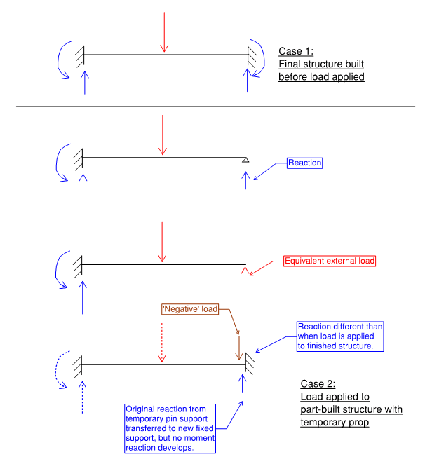
I may have confused things by posting a statically determinate example. Here's a trivial indeterminate example. Danielsp, I know you want to do something more complex and you've understood the principle - I'm posting this for others reading along.

Statical_change_indeterminate_n0yttn.png
 
Not even real code, RB. A simple spreadsheet will do.
 
Steveh, if I get it right it's missing a final stage of removing something. In my case it's always adding and removing beams or plates, but I suppose supports work the same way.
 
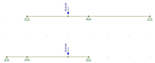
A closer example to what I am doing is this. Suppose I wanna transform the first structure into the second while loaded
Ideia_1_qevh9x.jpg


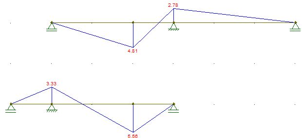
1) These would be the bending moments of the structures if built unloaded
Ideia_2_tiv2vu.jpg


2) So after loading the original structure, I build the new span and it looks like this (hinge not real, just added to create the real moment diagram)
Ideia_3_jwxwrt.jpg


Removing the right span would amount (to the remaining structure) to adding this load to this structure
Ideia_4_nnfcng.jpg


3) So these are the moments introduced to the new structure by demolishing the right side span
Ideia_5_cipoee.jpg


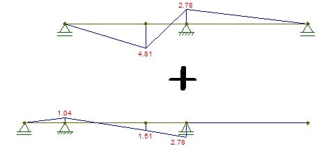
Therefore, we arrive at final moments by adding situation 3 to the original moments of the original structure
Ideia_6_qcevws.jpg

And the moments at the nodes would be 0; -1,04; 6,32; 0; 0

Hope I got it right, Seteveh
 
Status
Not open for further replies.

Part and Inventory Search

Sponsor