Continue to Site

Eng-Tips is the largest engineering community on the Internet

Intelligent Work Forums for Engineering Professionals

  • Congratulations IDS on being selected by the Eng-Tips community for having the most helpful posts in the forums last week. Way to Go!

Cheating section views. 3

Status
Not open for further replies.

swale2

Mechanical
Dec 29, 2009
44
Hello, I'm wondering if there is a method to take multiple sections views and stack them on top of one another? Also can they be constraint to one another. In the past the drawings were done in 2D SDRC I-deas drawings. In I-deas it is easy to cheat a view and over lay several sections of the a part over one another. For example the part could be a hollow shaft starting at 10 degrees it has 12 1/2" dowels equally spaced. In additional starting at 5 Degrees there are 4 holes 1.25- 8 tapped holes for lifting. The view I want to create is to capture both of these sections in the same view to save paper space. If I took two separate sections and overlay-ed them this can be done. Is there a way to constraint these views so they act as one? The view move together. In actually use I may have 4 or 5 separate sections all locked to get the one "cheated" view that was represented in the past. Thanks in advance. Also we are running NX 10.0.3.5 natively.
 
Replies continue below

Recommended for you

What we have done is overlay the 3D models in an assembly, and create the sections from this assembly. Not the answer you are asking but a different ways of doing things. If I remember in I-Deas this was a nice way of doing things.
 
SDETERS are you saying to have the same amount of for the example I used "Shafts" in an assembly and align each of them on a plane that the section is taken and this would show all the details in one view? This gets me there too. I'm not tied to the method just trying to replicate the past view with minimal effort with a model that can update and not require much manual tweaking. I like this idea.
 
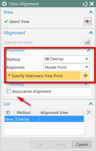
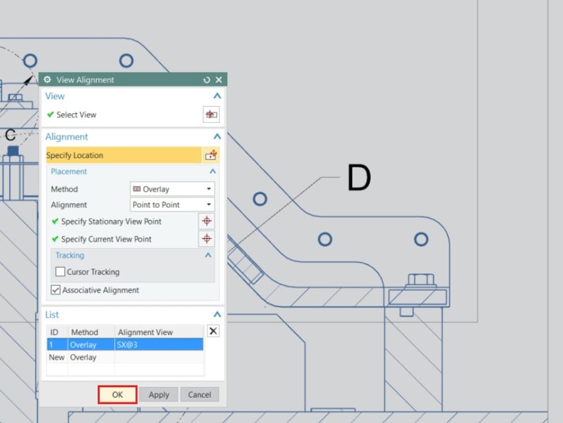
You can stack views on top of each other in NX. It is called "overlay" in view allignment.
overlay_vxhh2r.png


You can , with associativity, align views on top of each other.
NX will ask for the common point in your 3D model and aligns the views to that point.

Ronald van den Broek
Senior Application Engineer
Winterthur Gas & Diesel Ltd
NX9 / TC10.1.2

Building new PLM environment from Scratch using NX12 / TC11
 
Can you illustrate the original problem ?
How this model looks and the result you are after ?

Regards,
Tomas

 
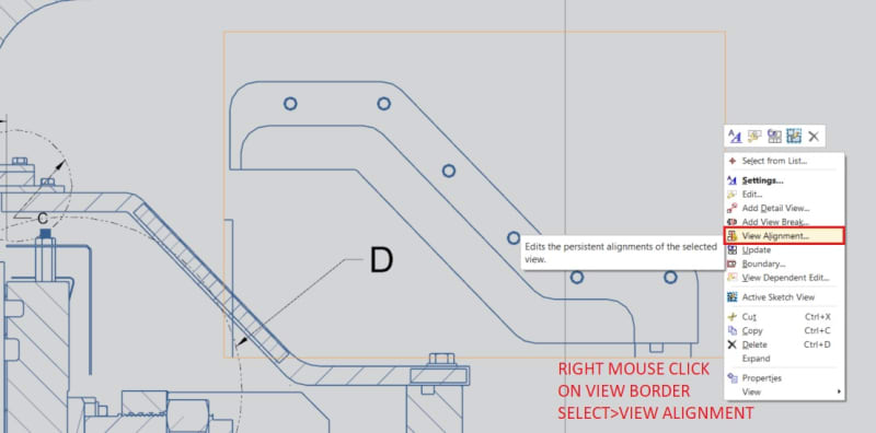
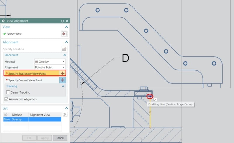
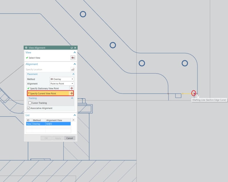
Thank you NutAce this is exactly what I was looking for. I had to use the point to point to get it to work though. The model view made my auxiliary view move off the page.


STEP_01_k4fre5.jpg


STEP_02_mexvgp.jpg

Select the fixed point on the "master view"
STEP_03_auvkjj.jpg

Select the mating point on the auxiliary view.
STEP_04_dg78r6.jpg

Views aligned

Prior to this I was manually aligning but if anything moved I had to manually correct. Acts as one view and you can adjust the view border to crop unwanted things in the auxiliary view.

Thanks again!
 
Status
Not open for further replies.

Part and Inventory Search

Sponsor