Eng-Tips is the largest engineering community on the Internet

Intelligent Work Forums for Engineering Professionals

Checking Variable Cross Section Corner Brace 2

Status
Not open for further replies.

MTSOE

Structural
Aug 25, 2023
18
0
1
CA
Hello.

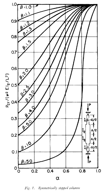
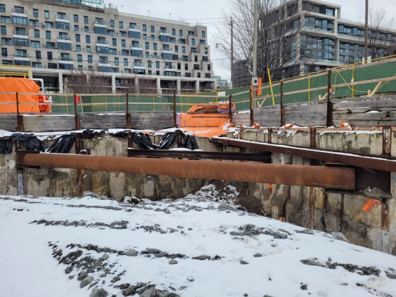
My company designs support of excavation and often incorporates steel pipe struts/corner braces. These members consist of pipe with pieces of wide flange slotted into the ends of the pipe. The purpose of the wide flange sections is to create a better welded connection to the vertical piles. Recently, a contractor accidentally cut a piece of pipe too short and asked if they could make up the length with longer wide flange sections. We told them to get a new piece of pipe and build what's on the drawings. But I was left wondering, how long could the wide flange sections be? Typically, we only check the axial capacity of the pipe and the weak axis buckling of the wide flange is ignored given the short span. But how would I go about checking a variable cross section compression member? I've found some papers on "stepped columns" and some useful formulas in Roark's Stress and Strain but I feel like a simpler check is eluding me. Does anyone have any ideas? I've attached a photo of a similar corner brace for your reference. Thanks
Resized_20240108_113440_34746670929295_pulw0k.jpg
 
Replies continue below

Recommended for you

There is no "simple check" for this, and although the buckling capacity is theoretically a function of the whole member length and its properties, a short wide flange at the ends would not change the global behavior by much, unless the buckling length changes radically (L increases by 15%: --> 75% of capacity) - the fact that pin-pin connections (which I guess you're using) are actually semi-rigid makes up for small differences in as-built and as-planned lengths.

With modern computers, it is trivial to calculate the buckling load with the finite element method. You can model the pipe and wide flange as beams (for the case in the figure, the connection would transmit primarily vertical shear and axial force) and apply pin boundary conditions at the ends in under 10 minutes. You can also solve the FE system by hand using. e.g., one element per strut and wide flange.
 
The stepped column check is your simpler check. Looking at those nomographs (from Dalal or others) should give a pretty quick indication of how much length each end can be a reduced moment of inertia without compromising much axial buckling capacity.

Dalal below, where alpha = A/L and beta = I2/I1
ColumnDalal_iqyee1.png
 
Nomograms can be useful, but I wouldnt use one for a buckling check without first validating it, and if you've done that, you may just as well make a FE model.
 
Do note that the nomogram by Dalal assumes a rigid joint between the struts of different area and second moment of area, which is not applicable to the strut you posted (welding a tube to a wide flange web will not create a rotationally stiff connection).
 
Though I have not quantified the rotational stiffness of the connection between the wide flange and the pipe with any sophisticated analysis, I can content myself that the connection can be approximated as a rigid joint. The web of the wide flange is slotted quite deep into the pipe (750mm is typical if I remember correctly) and continuously fillet welded along the outside joints between the web and the pipe.
 
MTSOE: in the transverse direction (out of plane bending of the wide flange), there is negligible fixity. The wide flange has a small minor axis bending stiffness and the tube is not connected to the flanges, implying that only the web (a plate with very small bending stiffness) resists the transverse bending. In the major axis direction, the tube is only connected along four welds to the wide flange web, which again does not provide fixity. You need to join the wide flange flanges to the tube to create a moment joint.

You may make a shell model and compare the results to the beam model with an assumed rigid and non-rigid joint to confirm what can be seen also by inspection.
 
The graph is good. I'd have done a buckling analysis before being shown that but a lot more work to show trends like B=50 falling off a cliff.

The connection in the photo will be fine for major axis bending because the forces are in the plane of the web. Minor axis will see web flexing but still better than completely ignoring the flanges. I would use stiffeners if the I-beams were longer like if the fabrication error was accepted but as is looks fine for the designed length.
 
centondollar, where the pipe diameter and the wide flange flat dimension are similar (as is common practice and shown in the photo above), the web is pretty firmly restrained by the adjacent flanges, and I would judge that there is some significant flexural restraint present, even in the weak axis of the wide flange. This would be shown by FEA or yield line analysis of the web element.

Is it a fully restrained moment connection (e.g. suitable for a building frame)? I don't know. But is it suitable to achieve unified axial buckling behavior? Yes.
 
Status
Not open for further replies.
Back
Top