Continue to Site

Eng-Tips is the largest engineering community on the Internet

Intelligent Work Forums for Engineering Professionals

  • Congratulations SSS148 on being selected by the Eng-Tips community for having the most helpful posts in the forums last week. Way to Go!

Circularity versus self-referencing circular runout

Status
Not open for further replies.

aniiben

Mechanical
May 9, 2017
158
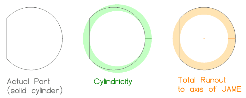
I read some discussions about self-referencing runout (circular and total) and I'm trying to understand why cylindricity could be considered "equal" to "self- referencing" total runout, but not the same thing could be said about circularity and circular runout.

No practical application. Just purely academic and theoretical discussion.

Also, I agree that "self referencing" should be avoided to eliminate any misinterpretation and inspection problems that must be overcome with non classical inspection techniques.


From different thread copy-paste:
"I agree that in case of total runout it would be equal to cylindricity, however for circular runout I think it is different from circularity and in certain, though very untypical, situations it may make sense. And I also agree that standard approach is to use runout for controlling feature(1)-to-feature(2) relationship, and not "runout being used on a single feature with a single self-referencing datum". " end of copy-paste.


Replies continue below

Recommended for you

aniiben,

aniiben 23 Apr 19 23:48 said:
I'm trying to understand why cylindricity could be considered "equal" to "self- referencing" total runout, but not the same thing could be said about circularity and circular runout.

Your initial question involved both cylindricity/total runout and circularity/circular runout, initially stating that cylindricity and so called "self-referencing" total runout were considered equal and supported it with a quote from pmarc, which you repasted. I would disagree with that quote from pmarc, I believe we established from other discussions that they are indeed actually not equal.

In regards to circularity/circular runout I think the below figure from Evan's post on (24 May 18 22:18) in the thread would apply as well since the axis about which circular runout is measured is still the UAME of the datum feature (in this case, this is of course the same as the UAME of the feature of interest). For cylindricity/total runout it would just apply over the entire feature surface, but for circularity/circular runout it would apply at each cross section.

Cylindricity_vs_Total_Runout_to_UAME_sdfuce_zbdhrp.png

All credit goes to Evan (axym) for this figure.

Thank you also for the note about incorrectly labeling the 2018 standard as 2019. Clearly as you can see from my many corrections that my brain was not quite working 100% yesterday, I should proof my work more.
 
Although I truly appreciate the trust that is put in me, I am kind of surprised that my statements from the other thread have been used in this discussion. I thought I clearly admitted then that I was not correct and that Evan's sketches fully convinced me.

In regards to circularity vs. circular runout thing, good example to show the difference could be for example the shape shown in fig. 5-4 in Y14.5-2009. If we imagine that in each cross-section perpendicular to the axis of the dia. 16.4 outer boundary the pin is perfectly circular, the measured circularity error will be zero, while the measured circular runout error (relative to the axis of the dia. 16.4 boundary) will definitely not be zero.
 
pmarc 25 Apr 19 15:17 said:
If we imagine that in each cross-section perpendicular to the axis of the dia. 16.4 outer boundary the pin is perfectly circular, the measured circularity error will be zero

Actually not to nitpick but sections wouldn't be taken perpendicular to the axis of the 16.4 dia outer boundary, but per the definition* the cross sections would be taken perpendicular to each point along the spine defined by the feature, right? So they could indeed be perfectly circular as you say.

Thank you for pointing out that figure - I agree this is another good example of the differences between circularity and circular runout, which can be even more pronounced than cylindricity and total runout. Although cylindricity does not require an axis be defined, the concentric cylinders which bound the tolerance zone naturally form one which in many cases might coincide with, or at least be very close to, that of the UAME axis utilized for total runout measurement. On the other hand, circularity has no such natural formation of an ideal axis and each section is instead taken perpendicular to the spine defined by the feature, while circular runout still utilizes sections taken perpendicular to the UAME axis. One can imagine from looking at 5-4 that these deviations can be quite extreme with high circular runout while showing zero circularity error.

*actually the definition mentions both axis and spine, but I am operating under the assumption that one does not get to choose - if the feature is curved the ideal axis is instead a spine.
 
Pmarc,

I have to admit that I am one of the members of this forum who trust your level of expertise without any questions asked. (more like “because pmarc said so”). Therefore, please don’t let me down.[wink]
I suspect they are many other to do the same (to a more or less extensive level)

Anyway, could you, please, indicate in your previous thread (the discussion within which Evan posted his figures) where you admitted that you were incorrect? I missed that part, hence I reposted your quote as a truly valid one. I am talking about the relationship (or lack thereof) between cylindricity and self-referencing total runout.

Thank you pmarc
 
chez311,
I knew you would nitpick ;-).

There is one reason (apart from the fact that the latest version of Y14.5 in fig. 8-10 specifically states that the cross-sections should be perpendicular to the axis of the UAME) why I decided to mention cross-sections perpendicular to the axis and not to the spine, and it is basically certain consequence of allowing the cross-sections to be perpendicular to a spine for nominally cylindrical features. The consequence is that the commonly known, widely accepted and explicitly given rule that the circularity tolerance value must be less than the size tolerance value (when Rule #1 applies) is not true any more in geometrical sense.

So if we take, for example, the upper right picture in fig. 5-7 in Y14.5-2018 (fig. 2-6 in Y14.5-2009), where all local sizes of the dia. 20.0-20.1 pin are at LMC and the pin is a banana within 0.1, and assume that the cross-sections for circularity error measurements are taken in planes that are perpendicular to the spine of the pin, I don't see why a circularity tolerance, if used, would have to be less than 0.1.

--------
greenimi,
pmarc said:
Evan, thank you for the sketches showing the subtle difference between cylindricity and what CH shown in his figure B.
This is where I admitted there is a difference between cylindricity and the scenario with so called "self-reference" total runout.
 
Thank you pmarc for the clarification. I missed your quote in that part of Evan's driven picture thread.


Pmarc said:
There is one reason (apart from the fact that the latest version of Y14.5 in fig. 8-10 specifically states that the cross-sections should be perpendicular to the axis of the UAME) why I decided to mention cross-sections perpendicular to the axis and not to the spine, and it is basically certain consequence of allowing the cross-sections to be perpendicular to a spine for nominally cylindrical features. The consequence is that the commonly known, widely accepted and explicitly given rule that the circularity tolerance value must be less than the size tolerance value (when Rule #1 applies) is not true any more in geometrical sense.

Pmarc,
I guess we agreed that UAME on circularity "picture definition" is an oversight in 2018 version.

Ignoring this fact, are you suggesting that it is a conflict within y14.5 regarding circularity definition and the physical reality? We discussed this before and I was under the impression that the conflict is only with the 1994 version of the math standard 14.5.1.

I know you said it before that a conflict with the physical reality within y14.5 is the DMLS RFS to be smaller than orientation/location. (Just because ASME said so)

Is this "circularity issue" another similar kind of conflict?
 
greenimi said:
Is this "circularity issue" another similar kind of conflict?

Yes, if we agree that for nominally cylindrical features the cross-sections are perpendicular to the spine.

No, if we agree that the cross-sections are perpendicular to the axis of UAME.
 
I guess circularity issue has been discussed recently (after the release of 2018 standard) and here is a quote from Evan :(
Evan said:
Interesting observation about the circularity description and the new reference to planes perpendicular to the axis of the UAME. It's hard to say what they were thinking with that, because there are conflicting indications:
-As 3DDave pointed out, this would exclude cones because they don't have a defined UAME (despite this, Fig. 8-10 includes an example with a cone)
-The circularity section in the text (8.4.3) does not mention the axis of the UAME. It refers to planes described in 3.6 (a) and 3.6 (b)
-3.6 (a) describes planes perpendicular to the axis or spine (curved line)

I would have to say that the cutting planes do not have to be perpendicular to the axis of the UAME, despite what it says in the Fig. 8-10 caption.


Also, I see your thread posted back in 2012 (when only 2009 version was in place)

pmarc,

Are you thinking that the committee deliberately added UAME for nominally cylindrical surfaces and that addition is NOT a mistake , as originally, I was thinking? ( I am talking about the verbiage under figure 8-10 / 2018)
Yes, basically I am putting you against Evan [bow], but I am trying to fully get your point of view about circularity.
[thanks2]
 
Pmarc, Evan and all,

And one more thing: don’t tell me that this circularity issue boils down to the ambiguous definition of the actual local size. (looks like the definition did not change).
2009
“ 1.3.54 Size, Actual Local
size, actual local: the measured value of any individual
distance at any cross section of a feature of size”
2018
3.57 SIZE, ACTUAL LOCAL
size, actual local: the actual value of any individual
distance at any cross section of a feature of size.

But in the math standard draft (which is to be released in the support of 2009) –see page 12 of the attached presentation) –a new definition is to be deployed (at least looks like).


Did you see any good additions (to support one approach versus the other for circularity) in the math standard?
 
I hope I haven't gotten myself a reputation! [upsidedown] I should have known you had your reasons and wouldn't have missed something like that - I had a feeling as such after I posted my reply.

pmarc 25 Apr 19 21:44 said:
the fact that the latest version of Y14.5 in fig. 8-10 specifically states that the cross-sections should be perpendicular to the axis of the UAME
I had forgotten I saw the discussion on this that greenimi referenced with Evan. I'm sort of in the same boat with Evan's opinion that greenimi posted - considering the definition in Y14.5-2018 para 3.6 is almost unchanged from 2009, the conflicting notation in 2018/8-10 seems strange but I don't think is sufficient to change how circularity is defined (ie: sections perpendicular to the spine). I don't want to dismiss this as an oversight (we all know THAT never happens....) but it seems like one if I ever saw it.

pmarc 25 Apr 19 21:44 said:
The consequence is that the commonly known, widely accepted and explicitly given rule that the circularity tolerance value must be less than the size tolerance value (when Rule #1 applies) is not true any more in geometrical sense.

So if we take, for example, the upper right picture in fig. 5-7 in Y14.5-2018 (fig. 2-6 in Y14.5-2009), where all local sizes of the dia. 20.0-20.1 pin are at LMC and the pin is a banana within 0.1, and assume that the cross-sections for circularity error measurements are taken in planes that are perpendicular to the spine of the pin, I don't see why a circularity tolerance, if used, would have to be less than 0.1.
Between this and greenimi's mention of actual local size, conceptually I see what you're talking about. Basically if sections are taken perpendicular to the UAME axis this separates circularity from the definition of actual local size, which is what dictates the requirement for circularity to be less than the size tolerance, right? Regardless, as above I am not convinced that the sections should be taken perpendicular to the UAME axis - and besides as you are clearly aware the requirement for the circularity tolerance to be less than the size tolerance is still explicitly stated in the body of the standard, regardless of what might be feasible geometrically. You said *you wanted to mention it for this reason, did you simply want to highlight this disparity between what would be possible geometrically vs. what is stated in the standard if the verbiage in 8-10 were not considered an oversight?

*Edit: removed repetition
 
After giving it some more thought I don't have strong enough arguments in support of the thesis that in Y14.5 the cross-sections shall be perpendicular to the axis of cylindrical feature's UAME.
 
Pmarc,

I see that you’ve erred on the side of the geometrical conflict due to the lack of support from Y14.5 standard itself and, maybe, other related standards (math Y14.5.1, but not only)

Since you have an extensive knowledge on ASME and also on ISO, I would like to ask: how would you define the circularity if you had the power to do some definition changes?

The DMLS (derived median line straightness) requires UAME and as we talked multiple times here and on linkedin site we are going in circles about these definitions. (back in the square one)

Again, my challenge to you, (if you can post your opinion on a public website): How would you do it ?

- Separate definitions for nominally cylindrical surfaces versus bent tubes/ garden hoses? (cross-sections oriented to UAME versus to the spine)

- No pre-defined orientation for the circularity tolerance zone? (specially now that the 2018 version changed the default stabilization procedure from candidate datum set to single solution to minimize separation) – 2018 states: “the default requirement is that the part be adjusted to a single solution that minimizes the separation between the feature and the true geometric counterpart”…

- Other solutions you can think of…

Thank you for your input
 
Pmarc and all,

I know that ISO are planning to change the definition of circularity or roundness in a future amendment to ISO 1101 (if they haven't done it already). The new definition will require the roundness tolerance zone to be perpendicular to the surface of the feature instead of perpendicular to the axis.
I read, in the same discussion, that this change will affect circularity or roundness tolerance applied to a non-cylindrical feature such as a cone.

Does anyone know if this update is in effect? ISO1101-2017 is already released but I do not have access to that document nor knowledge of this specific detail.


ISO 1101:2017 states that for cylindrical features roundness applies in cross-sections perpendicular to the axis of the toleranced feature, and for spherical features roundness applies in cross-sections that include the center of the sphere. That standard doesn't specify what exactly "the axis of the toleranced feature" and "the center of the sphere" mean, but by looking into other ISO GPS standards one may understand them as the axis of the associated LSQ cylinder and the center point of the associated LSQ sphere.

As for features other than cylinders (like cones or other revolute surfaces), 1101:2017 says that orientation of the cross-sections containing roundness tolerance zones must always be explicitly defined by the direction feature indicator. So, without going into details of what the direction feature indicator is, ISO offers methods to define that the cross-sections for roundness are to be perpendicular to the axis of the cone or normal to the surface of the cone or at any other defined angle.
 
One article about Roundness....Not sure if it is in up to date or not....but sure shown ISO has its own problems with this control (roundness / circularity) and not only ASME
(based on the fact has been debated for so long)

"The trouble with Roundness

09 / 06 / 2013

One of the geometrical tolerance characteristics is ‘Roundness’ (or ‘circularity’ if you are working to ASME Y14.5).

The way in which Roundness has always been defined is that it applies to the line element created in any plane perpendicular to the axis of the feature.

Thus roundness is measured perpendicular to the axis of the feature, and not perpendicular to the surface of the feature. This is inconsistent with other geometrical tolerances (e.g. run-out, profile, etc) which are all measured perpendicular to the surface.

While this works out just fine for cylinders (where perpendicular to the axis is pretty much the same as perpendicular to the surface), it does not always work out well for cones. The greater the angle of the cone, the greater the cosine error in any measurement.

For these reasons, a proposal was put forward in the ISO technical committee TC213, several years ago, to change the definition of roundness, so that it would be defined as a tolerance which applied perpendicular to the surface.

ADVANTAGES:-
•it makes more sense from a design point of view, when defining cones, as it is more likely to correspond to the type of variation which affects the functionality of the part.
•it makes more sense from a measurement point of view, as it will reduce measurement uncertainty.
•it is more consistent with the definitions of other geometrical tolerances.

DISADVANTAGES:-
•it is a change
•it introduces another difference between ISO and ASME
•the transition from the old definition to the new would require managing in industry (changes to working practice, changes to measurement procedures, changes to software, etc).

ISO have flip-flopped over this for a while. At first the change was going to be introduced, then it wasn’t. Every time it was discussed, it caused a great deal of debate. Eventually, a new definition for roundness was to be introduced in the 2012 revision of ISO 1101, but at the last minute there was another change of heart.

At the time of writing, the plan is to leave the definition of Roundness unchanged. As a way around this, an alternative proposal has been put forward, which is actually a rather elegant way of tackling the issue.

The idea is that if you need to control the ’roundness’ in a direction normal to the surface, you can specify this by using a Circular Run-out tolerance, with the feature used as its own datum. Although not an ‘illegal’ drawing indication under current rules, most experts in this subject would normally discourage this kind of practice, as it creates a ‘circular reference’. With just about any other tolerance characteristic (position, coaxiality, parallelism, etc), this would create a meaningless and uncheckable requirement.

Why is it different with run-out? Run-out tolerances have always covered a combination of geometrical characteristics. Applying Circular Run-out to a cylinder controls the combined effect of any roundness errors, and any coaxiality errors. By using the cylindrical feature as its own datum, the coaxiality factors are eliminated, leaving you with a roundness tolerance. Apply the same tolerance arrangement to a cone, and you have a kind of roundness, but applied normal to the surface of the cone.

Some kind of illustration covering this is likely to find its way into a future edition of ISO 1101 (unless people change their minds again)."


from :
 
Status
Not open for further replies.

Part and Inventory Search

Sponsor