Continue to Site

Eng-Tips is the largest engineering community on the Internet

Intelligent Work Forums for Engineering Professionals

  • Congratulations MintJulep on being selected by the Eng-Tips community for having the most helpful posts in the forums last week. Way to Go!

Circulating currents in banks of transformers with star-delta connection 3

Status
Not open for further replies.

diegoz14

Electrical
Sep 18, 2018
6
First of all i want to apologize for the grammatical errors, i'm not a native english speaker, but i really need help with this topic.

I'm an intern in the electrical company of my country, at the present time the company is focusing its efforts to reduce the technical and non technical loses in the distribution system, i was assigned the task of look into the behavior of star-delta connection transformers banks of high consumers, my job is basically use a amperimetric clamp and measure the currents of MediumV (34.5-13.8k)V side, LowV(480-120)V side and circulating currents, also power factor, impedance of the bank and position of the tap's selector. The electrical system in my country has been left behind for decades making it a non-regulated system until now, i often find customers with circulating currents in the LowV side, 8 times higher than the most high line current, note that almost all clients have unbalanced loads and power factor up to 0.9, what makes this to happen? if you see how much current enters in the primary and how much is out trough the secondary you can see heavy losses, what makes the banks to have this kind of behavior? the currents between phases shouldn't be line currents/√3 ? an unbalanced bank in delta will have phase currents higher than the line currents in an effort to "balance" the loads? I know that for a real analysis we need the angles of the currents, but with the information available, what conclusions can we obtain?

HERE YOU CAN SEE A GOOD EXAMPLES OF WHAT I'M TALKING ABOUT

client: ZIPPERs

total kVA: 225

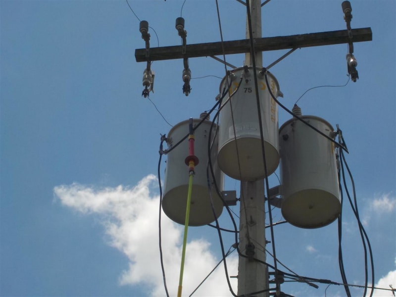
discriminated kVA : 1*75+1*75+1*75 kva

PRIMARY PHASE A CURRENT: 7.5

PRIMARY PHASE B CURRENT: 7.3

PRIMARY PHASE C CURRENT: 7.2

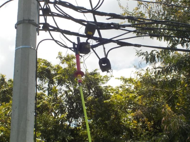
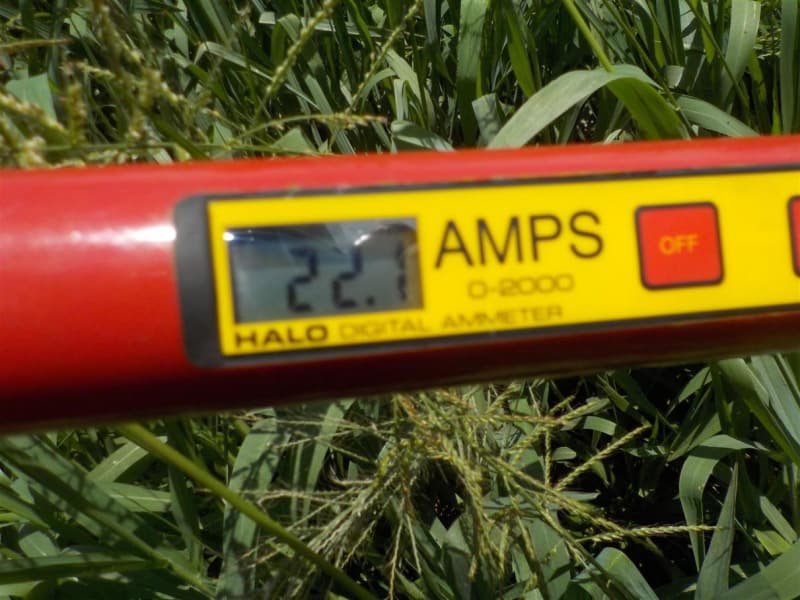
SECONDARY PHASE A CURRENT: 22.1

SECONDARY PHASE B CURRENT: 10.1

SECONDARY PHASE C CURRENT: 15.8

SECONDARY NEUTRAL CURRENT: 34.3

BRIDGE AB CURRENT: 230

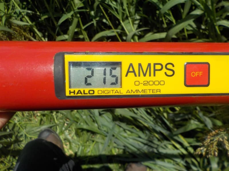
BRIDGE BC CURRENT: 215

BRIDGE CA CURRENT : 225

this is the "ZIPPERs" case, here we have a 3*75kva star-delta bank with a transformation relation of 13.8kV to 480/240 v , this bank is used to feed a poultry farm, if you see, the highest secondary phase current is just 22.1 A, meanwhile in the "bridges" that connects the individual transformers into a delta connection, the currents are up to 220 A , i don't know the angles of the currents nor the voltages, this is why i can calculate the real efficiency, if a use only apparent power the efficiency of this case in specific is only 7.22% , and this is not the only case where the efficiency is below than 50%.
DSCN9529_bzrubz.jpg
DSCN9530_mtdy3z.jpg
DSCN9519_naskwk.jpg
DSCN9520_nphv3f.jpg
 
Replies continue below

Recommended for you

Is this a grounded wye/delta? If so, these are notorious for circulating current caused by minor voltage imbalance. We float the primary neutral on these systems. This better balances the voltages and stops the circulating current. Two bushing transformers are required. Looks like yours may be single bushing.
 
stevenal said:
I really dont know how to reply directly to your comment, since i'm new in this forum ( i hope you'll read this comment), you see, the distribution net in my country is a wye with the neutral grounded every 100-150 mts,but almost all of the sample clients didnt have a ground wye in the primary side, they just connect the three individual bushings to the three phases of the distribution net, here is a interesting case: one client had a 300kva bank (3*100kva) 34.5kV/240 wye/delta pure, here we see a four "transformer" with a label that said "inductance transformer" this transformer was connected in way were the primary bushing was connected to the neutral of the wye (yes, this bank has a wye grounded) side of the bank meanwhile de secondary was grounded, i do a little research and found that this connection is basically a "petersen coil" a reactance tuned system that is related to the neutral regimen , the interesting thing about it was that this case was THE ONLY ONE in a sample space of 38 clients that has almost perfect circulating currents (line current/root(3) ) here are the data measure of this bank:

client: ROSALES

total kVA: 300

discriminated kVA : 1*100+1*100+1*100
PRIMARY PHASE A CURRENT: 3.4

PRIMARY PHASE B CURRENT: 3.9

PRIMARY PHASE C CURRENT: 3

SECONDARY PHASE A CURRENT: 456

SECONDARY PHASE B CURRENT: 436

SECONDARY PHASE C CURRENT: 422

SECONDARY NEUTRAL CURRENT: 0 (DELTA PURE)

BRIDGE AB CURRENT: 252

BRIDGE BC CURRENT: 286

BRIDGE CA CURRENT : 253


So, do you think this petersen coil has something to do with the excellent performarce of this bank?
 
diegoz14 said:
..they just connect the three individual bushings to the three phases of the distribution net..

So each can has one primary bushing. The non-polarity end of each primary winding is connected to the metal can, which is connected to the pole ground, which is connected to the primary system neutral and one or more grounding electrodes. This is a grounded wye primary setup. We use transformers with two primary bushings, with both ends of the winding fully insulated. Connect the non-polarity bushings together with no other connections for a floating wye neutral point.

After looking up Petersen coils, it looks like they may tend to limit unbalanced current returning to the system neutral, so may have a similar effect as floating the wye point.
 
Solutions:
1. Remove one primary fuse and let the bank function as an open delta.
2. Convert your clients over to wye secondaries.
3. Very often, the excess primary current will cause one primary fuse to blow. The bank then works well as an open delta. DON'T replace the first fuse to blow.
You may find a lot of transformer banks already working with one fuse blown.
Saves a lot of problems.
Where are you?
I may be familiar with your system. I spent over 15 years fighting with wye/delta problems.
Do you get a lot of customer complaints about power surges killing refrigerators and freezers?
That is a common side effect of a wye/delta system.
Do you have a lot of distribution circuits in the field protected by three fused cut-outs? That helps to kill refrigerators.
With wye/delta systems, your losses will be high, a short circuit on one phase may cause fuses to blow all over town. You will be plagued with customer complaints of burned out refrigeration equipment except in those cases where the customers has installed their own local protection.
The solution is to phase out the delta secondaries.
Anecdote.
I became the system engineer for a very small system. So small that system engineer was a part time job.
Short power failures were common. took several years to get all the three phase customers converted to wye secondaries.
Many times I would be in my room when the power went out.
The generators couldn't take the block loading of the entire system so the operators would go back online by closing fused cutouts, one at a time.
My room was often on the third phase to be energized.
When the first phase was energized, the lights would come on in my room on about 50% voltage.
With only "A" phase of a delta bank energized, we had a single phase circuit.
The "B" phase and "C" phase secondaries would be in series and would each get about 50% of normal voltage.
The would back feed through the primaries and energize "B" and "C" phase primaries at about 50% voltage.
Hence the dim light in my room.
Know that the operators would be out behind the plant in the dark; one holding a flashlight while his partner tried to get the pin in a telescoping hot stick into the hole in a cutout, 7 or 8 meters in the air. Sometimes it was raining.
Then the would energize "B" phase. Now the secondaries of "A" phase and "B" phase would act as an open delta and back feed through the "C" phase transformer to energize the "C" phase primary.
My light would get brighter.
Now we have one transformer bank feeding one phase of the whole circuit.
We have greater voltage drops and the transformer regulation both coming and going.
Then the third phase would be energized and my light would get a little brighter.
Consider the poor refrigerator.
It has been off for some time and probably wants to start. It gets 50% voltage. It makes a couple of turns and then stalls against the head pressure. After a few minutes of this abuse it is hit with almost, but less than normal voltage.
Still stalled. Most times the thermal protection would trip out but every time, one or two would expire.
Anecdote #2
I had left the country but was back for a visit. The manager of the Island utility got in touch with me and offered me and my wife a few days of holiday at the utility's expense if I would come out and walk around the system and make any comments I saw fit.
Guess what. There was a new wye/delta transformer bank.
" I thought that we were going to ban that connection."
"Yes, but this client is the National Telephone Company and they are too big for us to argue with."
"Tell me; Have you had any complaints about burned out refrigerators lately?"
"No. Not for years now."
"Would you like to go back to those days?"
"Never. That was awful."
"Well then we have to do something."
The first thing that I did was to do a load survey. I found a load of about 20 KVA on a 150 KVA transformer bank.
Over at the shop, we took a fuse holder for a fuse cutout. We removed the fuse link and tack welded the toggle in position.
Then the boys went out and switched the dummy for one of the fuses.
Everything worked as usual. The customer never knew the difference.
Burned out transformers.
Out of time. More later.
To come:
Anecdote #3> Human nature, and oversized fuses and burned out transformers.

Quick fix. Biggest bang for the buck.

Estimating losses.


Bill
--------------------
"Why not the best?"
Jimmy Carter
 
Grounding and neutral. There is a difference and the neutral may be grounded leading a neutral connection to often be called a ground connection. It is both but it is the connected neutral that causes the problems.

Estimating Losses.
Ballpark losses. I2R of circulating current. Estimate %R as 1/3 of %Z. but the zero sequence impedance is three time the positive sequence impedance so use the %Z for R in this case.

With secondary metering the client will not pay for any of these losses.
However in the event of transformer burnout, the customer may be liable to pay for the replacement. That is the big potential loss.

There will be losses on the higher voltage primary phases but this will be partially offset by the reduced current and losses on the phase conductor with the lower voltage.

Human nature, and oversized fuses and burned out transformers.
Wye/delta banks tend to blow primary fuses. It's human nature that after replacing the same fuse several time a larger fuse is used. Eventually the crews as a matter of course replace all fuses on wye/delta banks with larger fuses.
Eventually the transformer burns instead of the fuse.
The labor to continually replace fuses and the cost and labor to replace transformers is probably greater than the cost of the losses. We haven't mentioned lost production and possibly lost or spoiled product. Imagine a ton of frozen poultry thawing out and spoiling.

Remedy.
Get rid of the wye/delta banks.
The quickest and easiest is to first check the demand on the revenue meter. Compare the demand with the size of the transformer bank.
You will often find that the transformer bank capacity is 200% or more of what is needed.
Either remove a primary fuse or remove a secondary jumper and run in open delta.
If the bank is a four wire delta, 240 three phase and 120/240 single phase, keep the transformer feeding the single phase loads energized. That's the point of anecdote #2

Consider converting the client to 120/208 Volt wye service.
When changing the internal connections to convert a 120/240 Volt transformer to a 120 Volt transformer for use in a 120/208 Volt service be very careful of contamination of the transformer oil.
Do the work on a hot dry day. Make sure that your hands and wrenches are spotlessly clean.
One time this was being done and the hot transformer oil loosened a small drop of dirty grease from the thumb screw of an adjustable wrench. The drop was seen drifting away in the transformer oil.
That contamination was enough that a few hours later there was a flash-over on one of the high voltage leads.
Wash any tools that will be in the oil in good solvent. They must be spotless. try to avoid adjustable wrenches. It is too easy for some dirt to be trapped in the adjusting screw. An open end wrench is best as it is easy to clean and easy to inspect after cleaning.
Wear new medical gloves. Perspiration may contaminate the transformer oil and lead to the loss of a transformer.
Double check your internal connections. I saw a crew get the leads crossed. Rather than two windings in parallale they ended up with two windings shorted on themselves. When the fuse was closed for that transformer the whole world seemed to go HHUUUMMMMMM.
We could hear the diesel engine in the power station next door winding down and then it tripped off and everything was quite.

Note: As each wye/delta bank is converted to open delta or wye/wye, the issues with the remaining wye/delta banks may tend to get worse.
Hope this helps.


Bill
--------------------
"Why not the best?"
Jimmy Carter
 

waross said:
Where are you?
I may be familiar with your system. I spent over 15 years fighting with wye/delta problems.
Do you get a lot of customer complaints about power surges killing refrigerators and freezers?
I'm from honduras, about dead refrigerators we dont any complaints, because this connection is mostly used in high consumers clients, like poultry farms,coffee processors, industrial clients, factory etcs. for department buildings is commonly used a pad mounted trifasic transformer.


waross said:
With secondary metering the client will not pay for any of these losses.

yes, one solution that my superiors told me to reduce the losses in the system is to change the metering in the primary side, personally, a find this a little unfair to the client, they had to pay for energy that they don't use, this is one of the reason why I ask for help in this forum.

waross said:
Wye/delta banks tend to blow primary fuses. It's human nature that after replacing the same fuse several time a larger fuse is used. Eventually the crews as a matter of course replace all fuses on wye/delta banks with larger fuses.
to be honest, i dont know of many cases of wye/delta banks with blowing fuses, many because almost all clients have oversized banks, overload is a rare sight. (see the ZIPPERs example, a 225kva bank with secondary currents of 22.1 A working at normal operation.

waross said:
Get rid of the wye/delta banks.
so this and converting the client to a wye/wye configuration is the only remedy? because i dont think that the clients would be happy about one of the transformers they pay for it has to be disconnect, i mean its waste money, converting wye/wye connection may need a third party inclusion because my company only deals with the distribution, metering and billing of energy.
what about float the neutral like stevenal says? this will help to reduce the circulating currents in the jumpers and reduce the losses due to this? what do you think about it?


Regarding conversion to open wye/ open delta: Watch your loading. The capacity of two 75s is not 150, but about 57.7% of that. This is because unity power factor balanced loading will lead through one winding and lag through the other. If change out is required to get the capacity, I'd stick with the closed wye/delta; just use two bushing transformers and float the neutral. Open deltas tend to have unbalanced voltages, and we try to limit them to smaller motor loads. The wye point of closed wye/deltas is grounded temporarily when energizing the bank using single phase switching to avoid feroresonance.

I agree the best solution is wye/wye. This might be a tough sell to the customer, since they may need to change equipment or install step up transformers.

Open or closed wye/delta banks serving combined three phase and single phase loads tend to have one can larger than the other(s). The larger "lighter" serves all the single phase load as well as it's share of the three phase load, so it must be larger.

Here is a link to the various connections and framings
 
Steven. I agree that when serving large single phase loads such as one three phase service on a residential distribution circuit the single phase can is larger. It is also frequently an open delta service.
On the closed delta 120/240 Volt systems the loading is not as bad as it looks.
Consider a 100 KVA single phase load on the open delta formed by two 100 KVA transformers.
If you use vectors to determine the effective impedance and regulation of the virtual transformer formed by the open delta, you will find that they are equal to the third transformer.
When you put a single phase, 240 Volt load on any phase of a three phase, 240 Volt delta, 50% of the KW load is taken by the in phase transformer and 50% of the kW load will be taken by the other two transformers.
because three transformers are use instead of two in the open delta, the 58% derate is not valid.
The derate is 67%.
Each transformer takes 50% of the KVA load. (50% + (50% X 0.5 PF leading) + (50% x 0.5 PF lagging) = 100%

diegoz14. I thought I recognized the system.
I spent over 15 years mostly in La Ceibe and Guanaja.
Worked at the Corfino Mill near Corocito and At the Maderas Tucan mill at La Venta between San Esteban and Gualaco. (Rough country)
I also worked a lot for Belco out on Isla de Guanaja.

The refrigerator issue is not with the clients with the wye/delta services, it is with all the residential clients on the same circuit. Aceyco and other suppliers market small protection devices for refrigerators.
These may be plug connected and cut off on either over-voltage or under-voltage.
There is a few minute delay before they turn on.
The number of refrigerator burnouts is not as great as it once was because so many residential customers have bought and are using the protective devices.

Did you know that at one time an electrician or engineer bringing in a transformer order may quietly receive a mordita from the supplier. Transformers tended to be oversized to maximize the mordita.
Economics over engineering.

I believe that the customer is responsible to buy the original transformer but after a time the ownership passes to ENEE.
If the transformer fails, however, he may in some cases be responsible for the cost of the replacement.

In further regards to the energization issues; If the fuses are pulled at the plant and the transformer with the single phase loads is energized first, there will be no problem.

The problem is when the fuses for an entire neighborhood are pulled on Sunday to allow repair work to be preformed on dead lines. Any wye/delta banks on that circuit will abuse all the refrigerators on two of three phases.

A wye:delta bank may have some uses, sort of.
An anecdote that was shared with me by an ENEE engineer:
A three phase distribution line runs La Ceiba east about 36 km to Jutiapa. From Jutiapa two phases extend a distance east to pick up an fairly large Wye:eek:pen delta bank. There are also distributed single phase loads. The unbalanced current on the neutral causes voltage drops and phase angle errors.
There was a radio station I beleive) at Jutiapa with a wye:delta service.
The metering in the substation in La Ceiba always showed this circuit to be well balanced.
The radio station had been out of operation for some years, but the transformer bank remained energized.
Someone realized that the transformer bank was not in use and ordered it to be disconnected.
After the disconnect the metering showed the circuit to be very unbalanced.
This is a good practical example of a wye:delta bank using circulating currents to correct voltage unbalances and phase angle errors to the best of its ability. In this case it was doing a good job.

We had a similar but not identical situation at the Maderas Tucan Mill at La Venta. The distribution line was fed fro a substation at Juticalpa. Three phase were run from Juticalpa through Gualaco to our mill at La Venta.
The circuit continued with two phases to San Estaban and area. Of course there was single phase loading on the two phases as well as a fairly large open delta service.
This caused a lot of current on the neutral and voltage drops on both the neutral and on the phase conductors back to around Gualaco.
The voltages and phase angles at the mill were terribly unbalanced. We had a wye:wye transformer bank. Now the circulating current were in our motors. At times the mill would be shut down because a critical motor had tripped o overload due to the circulating currents.

This brings up another issue:
The reason for the unbalances which cause the overloads.
Uneven loading of distribution circuits.
I am remiss in that I did not first address attacking the problem at its source. Balance the loads on the distribution circuits.
Make sure that all the rural voltage regulators are working properly.

My focus was on the clients side and I did not have control over the ENEE primary side.
The first thing may be to try to balance the loads so as to avoid the unbalanced voltages and phase angles that give rise to the circulating currents.
I say, try to balance the loads because it is not as easy as it seems. Different social groups have different load profiles.
If we were balanced during the day, we were unbalanced during the night time and vice versa.

Do you have access to billing records?
Do you have access to KWHr meter data?
As a first step, you may select a circuit with a fairly severe circulating current and try to balance the other loads on the circuit. This will greatly lessen the circulating currents but will do nothing for the refrigerator issues.

The size of transformer banks and overloading.
The size of the transformer bank has nothing to do with The magnitude of the circulating currents.
the magnitude of the circulating currents is determined by the impedance of the transformer bank, the magnitude of the voltage and or current values and the impedance of the source.
If the impedance of the source is infinite, the impedance of the transformer is the factor, but on long lines, the line impedance adds to the impedance of the source.
Worst case is to base calculations on the impedance of the transformer alone.
A note on voltage unbalances.
Circulating currents may be caused by both voltage errors and phase angle errors.
Rural voltage regulators tend to make the circulating currents worse.
The rural voltage regulators do a good job of balancing the line to neutral voltages. In doing so they often cause or worsen line to line voltage errors and phase angle errors.
First, make every effort to balance the loads and the line to line voltages.
By the way, there was a long rural circuit running west of La Ceiba. a voltage regulator on one phase failed. It took out two transformers at the Lodge at Pico Bonito.
Good to talk to you, diegoz14.
Which part of the country are you in?

Bill
--------------------
"Why not the best?"
Jimmy Carter
 
Another thing. In the event of a ground on one phase and one fuse blowing, the wye:delta banks will backfeed into the fault. That is often when a fuse will blow on a wye:delta bank. This effect has been known for probably 70 or 80 years in North America. You can read about it in some very very old text books.
Once one fuse blows, the bank will continue to work as an open delta with no ill effects and no more circulating current.


Bill
--------------------
"Why not the best?"
Jimmy Carter
 
Stevenal.
Thank you for your contributions. Thanks for the link to the RUS standards. I had lost that and searched in vain for it.
As you will have noticed, this may be a somewhat special case and normal engineering recommendations may be over ruled by financial and political interests. And the financial interest may not be in the customers best interest.

Another possible solution.
Remove a jumper from one side of the transformer feeding the single phase loads.
That transformer will still supply the single phase loads and the three phase loads will be fed from the open delta.
Remember that this is an area where almost all distribution transformers are grossly oversized.
This may require one more conductor from the transformer bank to the single phase panel or to one phase of the three phase panel.
When a single panel is used with a wild leg, a second panel will be needed.

Bill
--------------------
"Why not the best?"
Jimmy Carter
 
THANK YOU SO MUCH waross you literally blow my mind with that example of the radio station i'd never thought that the problem could be the distribution circuit itself i see that i was thinking in a very little scale!
waross said:
Did you know that at one time an electrician or engineer bringing in a transformer order may quietly receive a mordita from the supplier. Transformers tended to be oversized to maximize the mordita.
Economics over engineering.
sadly this still happens a lot.

waross said:
I believe that the customer is responsible to buy the original transformer but after a time the ownership passes to ENEE.
If the transformer fails, however, he may in some cases be responsible for the cost of the replacement.

i'm not sure about the ownership passing to ENEE, right now ENEE is no longer in charge of the distribution system is a colombian third party (where i worked at) ENEE is in straight route to disband due to political and economical reasons.

waross said:
This is a good practical example of a wye:delta bank using circulating currents to correct voltage unbalances and phase angle errors to the best of its ability. In this case it was doing a good job.

how much energy do you think was lost due the bank was still energized?

waross said:
Do you have access to billing records?
Do you have access to KWHr meter data?
As a first step, you may select a circuit with a fairly severe circulating current and try to balance the other loads on the circuit. This will greatly lessen the circulating currents but will do nothing for the refrigerator issues.

yes i do have access to bot, you really gave me a good idea, i had two cases with severe circulating currents, and i can work with that circuits.

waross said:
Which part of the country are you in?
I´m from San Pedro Sula but my work covers all northwest part of the country (Cortes, Santa Barbara,Copan, Ocotepeque, Lempira, Yoro) but the worst cases of circulating currents are in san pedro sula and choloma city, the most industrial cities of my country, in SPS y Choloma wye/delta configuration is by far the most used when you have 3 transformers ,i'h see very few banks in a wye/wye connection, i often pay a visit to the substations in sps at different times of the day and the currents of the circuits are fairly balanced, now i wont be surprised if that is due all those wye/delta banks connected to the system.


I was in a seafood plant that ran supply ships offshore. Maybe Panama, but they would back-haul diesel fuel. Taxes unpaid.
It was cheaper to burn bulk priced, untaxed fuel than to buy from ENEE.
There plant was powered by three or four diesel generators.
Each generator was at the wrong voltage. If the panel was 120:240 Volts the generator was set for 480 Volts.
If a panel was 480 Volts the generator was set for 208 Volts or 240 Volts.
Someone must have done well on all those transformers.

I'd be happy and even excited to help you on this project for old times sake.
It brings back fond memories of the nice and fun place that Honduras was before Mel Zalaya left the country and things went down hill.

On information sources:
Have a talk with someone in the meter department. Revenue meters can record a wealth of information.
They may be programed to save voltage per phase, current per phase, kW demand, KVA demand, and probably a few other parameters. It's been a while. My friends at ENEE could give me a floppy disk with all those values, at 15 minute intervals going back a month.
The information helped solve several customer issues.
Twice, the ATF would not retransfer when the power returned. Problem: chronic low voltage on one phase.
Solution: change the settings on the ATF control board to allow a retransfer with a lower voltage on one phase.
Once, Power bill was too high. Problem: Faulty KWHr meter. Solution: Review data with ENEE billing department. ENEE billing department acknowledged the issue, changed the meter and issued a fair adjustment to the bill.

Suggested course of action to reduce circulating currents.
Pick a circuit to work on.
Get one or two months of detailed data. You may have to request the meter department to program the meter to save the data that you want.
Group your customers into similar load profiles.
Groups;
Residential, peak in hot weather during the day. Possible peak in the afternoon as supper is being prepared.
Commercial Monday to Friday.
Commercial Monday to Saturday.
Commercial Monday to Sunday.
Industrial, one shift.
Industrial two shifts.
These are examples only. When you get the data, form the groups as best you can.
Then work on each group individually to balance the load of that group across all three phases.

Losses. I2R. find the circulating current as best you can. Send a technician to the warehouse with a multi-meter to measure the resistance of the windings of several sizes and voltages of transformers.
Use the circulating current squared times the secondary resistance times three to estimate the secondary losses.
Divide the secondary circulating current by the transformer ratio to arrive at the primary component of the circulating current.
Use the same I2R but just times two.
Justification. this is just a little better than a WAG (Wild ASSumption Guess).
The actual heating is based on both the circulating current and the load current.
On the primary, under certain conditions one phase current may be zero. Hence times two instead of times three.
To that is added the losses of the line conductors.
You may compare the KWHrs supplied to a circuit in a unit time with the sum of the individual KWHr consumptions of all the users on the circuit. The difference will be the total losses, normal operation losses and circulating current losses.
Correct the balance to eliminate most of the circulating currents and see how much your total losses are reduced.
That is: The most accurate way to determine the circulating current losses is to correct one circuit and measure the difference.

Are they still using the old diesel generating station in La Ceiba to supply KVARs to the system and hold the voltage up during periods of heavy loading?

Your English is very good. Which school did you go to in Honduras?, What city?

Bill
--------------------
"Why not the best?"
Jimmy Carter
 
waross said:
Have a talk with someone in the meter department. Revenue meters can record a wealth of information.
I'm actually in energy control department, i have plenty access to all those data anytime, so often i go to the clients meters to download the load profiles, even the load profiles of the circuits in the substations.

waross said:
Suggested course of action to reduce circulating currents.
That's a excellent idea, i have a vague notion of what curse to take, but you gave me a much detailed plan.

waross said:
Are they still using the old diesel generating station in La Ceiba to supply KVARs to the system and hold the voltage up during periods of heavy loading?

I think that those generators are already closed, in the last 10 year a lot of new power plants (mostly privates) have been build up, in fact in the last month a new bunker power plant was set in the Sambo Crek community to help reduce the constant blackouts.

waross said:
Your English is very good. Which school did you go to in Honduras?, What city?
thak you, but i'm still lacking in many skills, i was in public schools all my life , even at the university, my English was self learned, this is why i have many flaws.

waross said:
I'd be happy and even excited to help you on this project for old times sake.

I'd be thankful if you can help me with this, in fact if this research show favorables results i'm planning of posting it as a science research in the articles section of my home university, my main goal is to help reduce losses in the distribution system (Losses are about 26-30% right now), but i dont want the cost of this losses to be transfer to the clients who have this kind of banks (using primary side metering) so if i can demonstrate that circulating currents are a directly consequence of the unbalanced distribution circuits and not a client's fault, that would make a big difference.
 
I am going to be away from home for the next 5 or 6 days. 2 days driving each way.
I will be active again later next week.
I will be in touch.

Bill
--------------------
"Why not the best?"
Jimmy Carter
 
I preparations for further discussions, consider researching the operating tariffs and ownership of the transformers.
I remember ENEE making changes to a circuit in La Ceiba and asking my customer to pay for new transformers.
I was involved in the discussions but I do not remember the details or the final outcome.
I do remember that the day that the transformers were changed was the day my son was born. I was back and forth between the hospital and the jobsite all day.
Consider a Public relations campaign to put pressure on the large consumers.
"Changes are coming to drastically reduce the number of power surges and failed refrigerators."
On the other hand that may be a two edged sword. It may be seen as an admission of responsibility.
It is worthy of discussion.

Bill
--------------------
"Why not the best?"
Jimmy Carter
 
A thought, Any customers resisting changes may be changed to primary metering. This would make them responsible for the losses and in cases where the circulating current was so severe as to cause a back feed, a penalty could be charged.
The point is to make it cheaper to cooperate with changes.
More discussion needed.

Bill
--------------------
"Why not the best?"
Jimmy Carter
 
waross said:
I preparations for further discussions, consider researching the operating tariffs and ownership of the transformers.

roger that

waross said:
I am going to be away from home for the next 5 or 6 days. 2 days driving each way.
I will be active again later next week.
I will be in touch.

I will be waiting, have a safe trip and thanks again!
 
I have internet and a few minutes in the motel.
A thought.
Resolving those primary, secondary and jumper currents with just an ammeter and no information about phase angles is something I may ask an intern to do as a bad joke.
However, not to say that you have been set up, just to suggest the futility of the job that you have been given and the tools you have to use.
A suggestion:
At Zippers or a similar client, record the primary, and secondary line currents as you have done. Record also the current in the jumpers between the transformer secondary bushings that show the high circulating current.
Check that the transformer bank is near 175% oversized. For a short time, 140% or 150% oversize will do.
Use the KVA demand on the meter to check the load.
Pull one primary fuse and record the new readings.
This will interrupt the circulating currents and leave the true load currents.
The primary currents will be skewed by the open delta connection, but by using the secondary currents and the transformer ratio calculate what the primary currents would be with a three transformer connection.
You should see a dramatic difference in the current.

With a transformer ratio of 28.75:1 the primary current for a secondary load current of 15 Amps should be less than an Amp.
Although your primary currents will be affected by the open delta connection, you will be able to see a dramatic reduction in primary current when the circulating current is removed.

The way to attack this problem and show good results may be to make a change and compare the difference.

Reality check; 75 KVA transformer at 480 Volts:
75000 VA / 480 Volts = 156.25 Amps.
Some of those jumpers will be showing the total current through one transformer secondary.
Over 200 Amps is a little harsh for a transformer rated for a full load current of 156 Amps
P.S/ you have lots of capacity to safely go open delta and eliminate the circulating currents.
After taking the measurements you may elect to leave one fuse removed.

Bill
--------------------
"Why not the best?"
Jimmy Carter
 
Back for a few minutes.
Are these calculations correct?
75 KVA = 75000 VA
75000 VA / 13800 Amps = 5.43 Amps, Full Load Current.
7.5 Amps, 7.3 Amps and 7.2 Amps is scary.
Trying to calculate loading, PF, losses, adding currents at different phase angles. Very difficult with the equipment that you have.
Let's think outside the box and see what we can do with what we have to work with.
We can work with I2R. That doesn't need phase angles and high voltage metering.
Then we can use subtraction. Keep the arithmetic simple.
If the current changes, the primary and secondary losses will both change in a square ratio.
Example; If the primary current is halved,the secondary current will also be halved. The I2R losses will drop to 1/4.
We can show some dramatic ratios.

Your primary losses can be represented by (7.5 Amps 2 x R) + (7.3 Amps 2 x R) + (7.2 Amps 2 x R)
= (56.25 x R) + (53.29 x R) + (51.84 x R)
= 161.38 x R Losses with circulating currents
Now pull one of the primary fuses.
Working backwards from the secondary currents (I will use an average of 15 Amps of load current. You will get the actual current from on site measurements.)
15 Amps @ 480 Volts = 0.52 Amps at 13.8 kV.

Now the primary currents on two transformers will each be about 0.5 Amps.
0.52 + 0.52 = 0.25 + 0.25 = 0.5
Now our transformer losses will be in the order of 0.5 x R Watts
Subtract our losses without circulating currents from our losses with circulating currents and we get
161.35 x R minus 0.5 = 160.85 x R Watts
So we have circulating current losses = 160.85 x R Watts
The losses with circulating currents are (160.85 x R Watts) / (0.5 x R Watts) = 321
The transformer losses with the circulating currents will be 321 times the transformer losses without the circulating currents.
I'm out of time.
Despite the high ratio the actual losses in Watts may not be as dramatic. However, if the instruments in the substation are of sufficient sensitivity you may see a drop in Watts when you pull a fuse.
When I get some more time, I will suggest some ways to get a reasonable estimate of the Resistances involved so we can look at actual Watts losses.
And be aware that the line losses will be less with less primary current, but not a lot of Watts.
I hope that you can get back to me with some readings soon.
Note; With an open delta on A phase and B phase, all of the load currents must pass through the transformer. There will be a 1.73 factor on the common phase, but not so on the open phases. The primary current will be equal to the secondary current divided by the transformer ratio. No other factors. The current is supplied by only one winding, not two windings at different angles. It makes the arithmetic easy.
Get me some primary current readings, with all fuses in and with one fuse pulled. Thanks.
Talk to you soon.
Hope this helps.

Bill
--------------------
"Why not the best?"
Jimmy Carter
 
Status
Not open for further replies.

Part and Inventory Search

Sponsor