Continue to Site

Eng-Tips is the largest engineering community on the Internet

Intelligent Work Forums for Engineering Professionals

  • Congratulations waross on being selected by the Eng-Tips community for having the most helpful posts in the forums last week. Way to Go!

CMU Wall Opening with W Shape Lintel

Status
Not open for further replies.

IlliniPE

Civil/Environmental
Jun 19, 2023
35
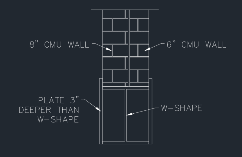
I have a client that is wanting to open up a CMU wall for as long of a span as I'll allow. Typically, I would just use angles for a lintel for the opening, but this wall is a combination of one 8" block wall and a 6" block wall, leading to an overall wall thickness of 14-15". I know I can find W shapes with this flange width, but I have major reservations against using the flange to support a wall instead of aligning with the web due to flange buckling and torsion. I have thought to add a plate to the outside faces of the steel to essentially make a steel section resembling a hollow CMU block.

Has anyone done design for eccentric loading on a W-shape or know of a design guide for it?
 
Replies continue below

Recommended for you

AISC DG9 - Torsional Analysis of Str. Steel Members
Enercalc has a steel beam under torsion module

I would go with an HSS tube instead if you're expecting torsional loads and can't brace the bottom flange of the W beam at all. Plus, if you plan to weld plates to close out the W section, that is just a tube but more expensive.
 
Why not add stiffeners to the web until you're comfortable that the flanges won't fail?
Then it's a matter of resolving the torsion at the end of the lintel, perhaps with an HSS post?
 
WesternJeb said:
I would go with an HSS tube instead if you're expecting torsional loads... Plus, if you plan to weld plates to close out the W section, that is just a tube but more expensive.
In either event, there would be some shape combinations as I'll have to use an angle on an HSS to give the CMU wall something to "sit in". I do think that would be cheaper though.
 
Suggestion 1 (what I have done in the past):
1. design the shape you need (smaller than the width, maybe only 8" wide).
2. Stitch Weld a steel plate over the top of the column

Suggestion 2:
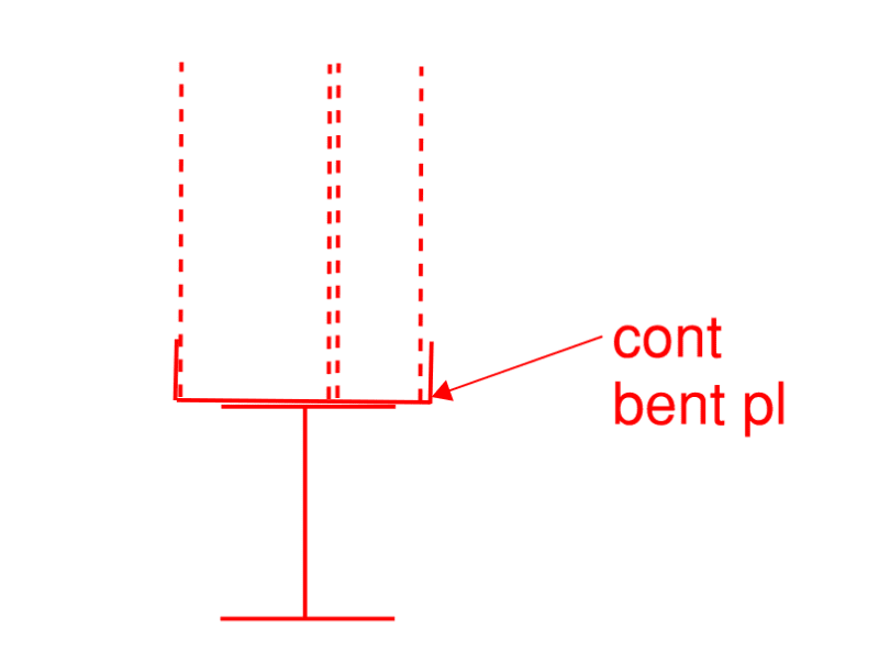
Use a shape of the correct thickness with only a 1/4" thickness so the bend radius on the ends is only 3/4" thick or so. I believe only having a 3/4" overhang is acceptable for CMU and Brick.

Keep in mind you will need to resolve the forces at the end connection, regardless of shape used. STI institute has a great guide for these connections.
 
atrizzy said:
Why not add stiffeners to the web until you're comfortable that the flanges won't fail?
I am going to have to add something to the flanges either way to give the CMU wall something to "sit in". I had thought to continue the plates on the outside face of the flange up a few inches to achieve this, but I suppose I could just use angles and stiffen up the flanges that way. I plan on using HSS posts to support it. I may just use HSS for the entire framing system per WesternJeb's recommendation.
 
How about a weak axis wide flange beam ?
Tbh I'm not really sure what your concern about using a strong axis wide flange is. If you put stiff plates ea side at 24 in o.c. the flanges would be more than capable of bearing the wall.

 
Disagree with DriftLimiter.

Stiffener plates keep the web/flanges from buckling on a local level. Stiffener plates do not limit global beam rotation / torsional failure.
 
driftLimiter said:
Tbh I'm not really sure what your concern about using a strong axis wide flange is.
My concern is I've never done it [lol] I'm not sure what complications arise with flange buckling due to load eccentricities. I can check torsion easily. I suppose it's no different than a plate analysis.
WesternJeb said:
Stiffener plates do not limit global beam rotation / torsional failure.
Agreed, but that can be checked pretty easily. Flange yielding is my primary concern.
 
I have gone through this exercise a handful of times and rarely get away with just a wide flange, personally. This is due to both the connection, as well as global beam rotation that isn't acceptable as it would be permanently tilted at an angle. Even if the strength is fine for a WF beam that is tilted at an angle, this doesn't pass my serviceability sniff test.

I, and others in my firm, just default to HSS tubes whenever a torsion connection / loading is required and we can't brace the bottom flange of the beam.
 
What about doing two separate beams, one for the 8", one for the 6"?
 
WesternJeb said:
Disagree with DriftLimiter.

Stiffener plates keep the web/flanges from buckling on a local level. Stiffener plates do not limit global beam rotation / torsional failure.

I didn't mean to imply that the stiffeners would resolve a torsional issue. I just dont see where the torsion is coming from.

If you know the centerline of the wall mass and you align the beam web with that then theres no torsion.

Perhaps a sketch? Is the WF beam to go below the wall? On the side? Where does the torsion come about exactly?
 
WesternJeb said:
This is due to both the connection, as well as global beam rotation that isn't acceptable as it would be permanently tilted at an angle.
That is a very good point. Do you use angles to provide something for the wall to sit in or do you leave it exposed?

jayrod12 said:
What about doing two separate beams, one for the 8", one for the 6"?
That isn't out of the realm of possibilities. Only issue I can currently see with this would be to make sure to get the deflections pretty close to protect the finishes. I believe that is doable, though.
 
IlliniPE, I agree a sketch is needed.

What is your end connection? Is it bearing on a CMU wall (in line with what is supported above) or a steel column support? This could change your approach of determining the respective eccentricities and ergo torsions.
 
Use two separate beams, one for the 8", one for the 6", with the same heights and weld the upper and lower flanges together.
 
WesternJeb said:
IlliniPE, I agree a sketch is needed.
driftLimiter said:
Perhaps a sketch? Is the WF beam to go below the wall?
I believe I attached it correctly. This will be the cross section.

WesternJeb said:
What is your end connection? Is it bearing on a CMU wall (in line with what is supported above) or a steel column support?
I typically use angle/plate and bear on the CMU wall for shorter spans, but I believe these circumstances will require a steel column support.

Sample_Support_dqt6as.png
 
You could also use a smaller flange WF beam and have a welded plate along the top in your detail above. This would prevent the cost of a WF with 14" or 15" wide flanges if a smaller beam works.
 
For a double wythe like that I'd likely use two members. A W shape for the interior one and an HSS for the exterior, just to get a thermal break.

-----*****-----
So strange to see the singularity approaching while the entire planet is rapidly turning into a hellscape. -John Coates

-Dik
 
Why would a simple wide flange beam with welded top plate like haynewp suggests, something that's very common, not work here? Where are all of the concerns about torsion coming from? Are these two walls loaded separately? If this was 10" CMU and 4" brick I don't think anyone would put this much thought into it.
 
Status
Not open for further replies.

Part and Inventory Search

Sponsor