Continue to Site

Eng-Tips is the largest engineering community on the Internet

Intelligent Work Forums for Engineering Professionals

  • Congratulations IDS on being selected by the Eng-Tips community for having the most helpful posts in the forums last week. Way to Go!

Cohesive Behavior in ABAQUS Standard

Status
Not open for further replies.

Eng.SaTa

Aerospace
Aug 6, 2021
19
I have a scarf joint, modeled in 2D ABAQUS . Two similar laminates (20 plies, symmetric laminates) are bonded together using adhesive. A picture of the assembly is attached. It's under a tensile load from one side and the other side is encastred. I have defined cohesive contact for the interface between left adherend (red part) and adhesive (green part) and a Tie constraint between right adherend and the adhesive.
I use ABAQUS standards/ static/general NLgeom step. Element type is CPE4.
When I define cohesive contact based on damage properties of adhesive, the model works, and I can easily plot RF-displacement and verify the paper which is my reference, but when I use composite damage properties to define cohesive contact, the reaction force at RF- displacement curve just goes up and the model has difficulty to converge!
This weird behavior is observed even when I insert an artificial flaw in adhesive-adherend interface.
Contact penalty stiffness is 1e+6 for both contact cohesive behavior.
I chose the softer material as slave and the element size of slave surface is finer than element size of master surface.
The point of maximum load based on composite properties reported in the reference paper is in agreement with the point my model starts to behave weirdly! Do you have any idea what's going wrong? is it sth related to damage progression properties or element type and size or time increment?!
Thanks for your help, in advance.
RF-Displacement_jjgybr.jpg
Table3_cj86te.jpg
 
Replies continue below

Recommended for you

Have you tried using cohesive elements instead of cohesive contact behavior ? Can you share the title of this research paper that you use for reference ?
 
I would try refining the mesh first. Apart from that, consider adjusting the damage properties slightly to see how the model behaves when they are changed in a particular way. If there are any settings not described in this article, try modifying them too.
 
Thanks for your help.
Using meh refinement, defining a new material orientation and adjusting some features of contact property definition, I could solve my problem for cohesive interface containing pre-existing cracks. But I have still some difficulties for the model without a flaw in interface.
I've already tried different viscosity stabilization coefficients in addition to various dissipation energy factors to stabilize my solution for nucleation a crack in a pristine cohesive interface, using composite damage property. None of them worked so far! What would be the other factors that can influence the stability and instability of the solution?
 
Apart from damage stabilization in cohesive behavior settings for contact, you can try using automatic stabilization defined in step settings. It often helps with convergence issues in such analyses.
 
I have already tried the option and it doesn't work!
I observed another wired behavior in the result, I want to share with you and will be more than happy if I can have your opinion.
As I said before, I encastred one side of my structure and applied a displacement to the other side. The reaction force on the constrained boundary in comparison to reaction force on the loaded edge is attached. As you can see, the RF on constrained end, behave as I expect, the Reaction Force drops as it reaches it maximum value!
Besides, the crack initiates and grows as you can see in attachment. I mean there is no difficulty for solver to nucleate the crack and then make it propagate along the defined cohesive interface!
But the static equilibrium we expect does not happen!
I also applied displacement loading to both end to see the effect of loading. This time, the RF curve for both ends goes up as you can see in attachment.
That's a numerical error but I cannot figure out where it stems from.
Is there sth wrong with loading condition?! Shall I change my solver from static to implicit dynamic or explicit dynamic?
FYI, I considered single fracture mode to alleviate anisotropic material effect and nothing changed. The wired behavior is still observed!
I do appreciate any help, any idea to solve the issue!
 
 https://files.engineering.com/getfile.aspx?folder=b07b6e04-5a39-4228-be50-cca98f56fb9f&file=New_Microsoft_Word_Document.pdf
Yes, it's definitely a good idea to try running this analysis with different solver. Especially that there are some convergence and stability issues here.

Can you attach a picture showing the whole model with boundary condition and load symbols (as displayed in the Load module) ? Just to make sure their definitions are correct.
 
I will try other Solvers and will let you know of the result!
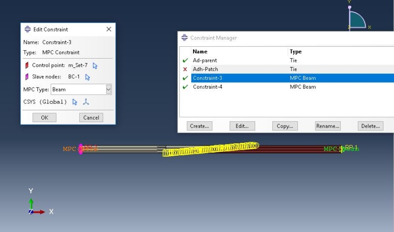
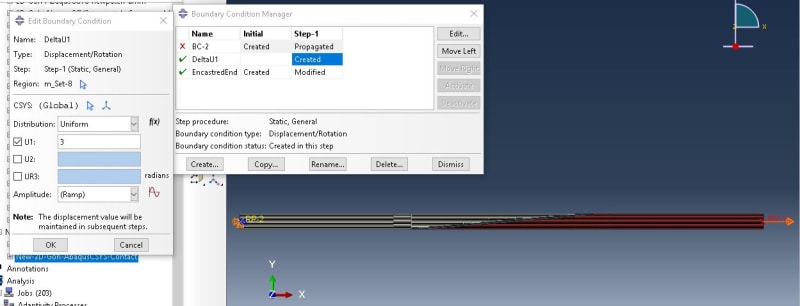
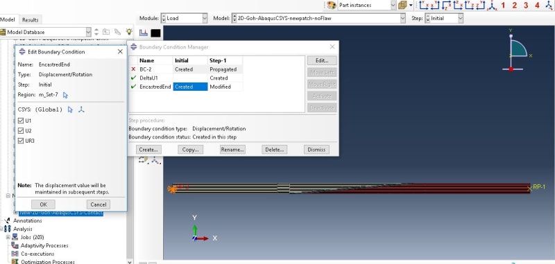
Meanwhile,you can find BCs and load as attached images.
Reference Point 1 and Reference point 2 are constrained to the ends of the specimen via MPC and load and BCs are defined for those points.
MPC-1_xnxicn.jpg
U1_hgjzeg.jpg
ClampedEnd_zu2zkx.jpg
 
Hi there,
I tried dynamic,explicit solver and it's running right now!
I faced a problem during simulation and I'd be glad if I can have your opinion on it!
Actually I think I haven't completely understood the General Contact yet!
Here is my difficulty with this type of CONTACT!
As I have already told, in ABAQUS standard, I defined a contact pair using cohesive behavior between the left adherend and the adhesive and a Tie constraint between the right adherend and the adhesive.
{Now I am asking myself, shall I change the Tie constraint to some other contact type at implicit solver?! Did I define the correct kind of interaction between right adhened and the adhesive?!)
By the way, I defined the Tie constraint between right adherend and the adhesive similar to ABAQUS standard and used general contact-> all with self -> exclude right adherend surface and right side of adhesive from the contact -> used a tangential contact as Global property Assignment and used individual property assignment to assign cohesive contact to my desired surfaces (left interface). But faced an Error as below:
"VALUE FOR ELIGIBIL IS NOT ONE OF THE LEGAL STRINGS. PLEASE CHECK FOR THE ALLOWABLE VALUES OF THIS PARAMETER IN THE USERS MANUAL."
To solve the issue, I removed Tie constraint between right adherend and adhesive and defined their interface as cohesive interface too and the program start running!
Now, my question is, how shall I define a perfect bond between two surfaces (such what Tie constraint does) while I am using General Contact between my assembly surfaces?
As Always, I appreciate your answers.
 
This error is related to Edit Contact Property --> Cohesive Behavior --> Eligible Secondary Nodes option. Check what is set there. If it's set to "Specify the bonding node set in the Surface-to-surface Std interaction" then you have to uncheck it as this setting can be used only in Abaqus/Standard.
 
I had unchecked that but still faced the Error
 
The same error ? What is the setting of "Eligible Secondary Nodes" now ? Have you tried other settings ? The error appears to be directly related to this option.
 
Yes, the same error happened
I tried default and slave nodes initially in contact options, but same error happened!
I guess it was related to Tie constraint defined for the other interface. Because When I removed the tie constraint and defined another cohesive contact for that interface the abaqus start to run! It's still running
Does Tie constraint have interference with General contact?
 
There should be no overconstraint because Abaqus automatically excludes contact pairs and tie constraints from general contact domain. Try running this without manual exclusion and individual property assignment.
 
Thanks @FEA way
I am still wondering why the reaction force at one end is dropping down and on the other end is going up?
 
Dear FEA way,
Finally my model converged. The problem caused by negative eigenvalues of stiffness matrix, resulting in " FORCE EQUILIBRIUM NOT ACHIEVED WITHIN TOLERANCE" and made the solution locally unstable. I specified the damping factor 1e-6 instead of using default dissipated energy fraction and it worked.
For more information, you an check article below.
Anyway, many thanks for your help and support :)
 
Status
Not open for further replies.

Part and Inventory Search

Sponsor