Continue to Site

Eng-Tips is the largest engineering community on the Internet

Intelligent Work Forums for Engineering Professionals

  • Congratulations KootK on being selected by the Eng-Tips community for having the most helpful posts in the forums last week. Way to Go!

Coil wire - maximum current? 1

Status
Not open for further replies.

RayJohnson2

Mechanical
Jun 22, 2015
32
Hi all,

I am designing an electromagnet, a coil, with roughly the following specifications:
- diameter about 30 mm, length about 40 to 50 mm
- maximum field strength: 50 mT (500 Gauss)
- AC, 0 to 330 Hz
- environment temperature: 150°C
- core: mu-metal
- winding: copper enamelled wire, diameter around 0.25 mm (SWG 33, AWG 30)
The biggest question I have is: what value could I use as ampacity? What is the maximum current that I can use on this wire, at this temperature?
I have found tables, listing max. currents at high temperatures, but that was for power cables. Not for small diameter wires like the one I mentioned.
Can anyone point me to data or tables?

Another question:
I usually use a coil winding fill percentage around 65% (Meaning 65% of the coils cross section is copper, 35% is not).
Does that seem realistic to you?

Kind regards

 
Replies continue below

Recommended for you

Current limit will depend on the 'on time'. What is the mas temp that your insulation will handle?
65% seam a bit low, but unless these are very carefully wound that may be right.

= = = = = = = = = = = = = = = = = = = =
P.E. Metallurgy, Plymouth Tube
 
>Current limit will depend on the 'on time'.
--- The duty cycle is currently unknown. But the AC current is a sine wave, so the average current is lower than the peak current.

> What is the mas temp that your insulation will handle?
--- The maximum temperature for magnet wire that I can find seems to be 240°C, but probably safer to use 200°C as a limit.

>65% seam a bit low, but unless these are very carefully wound that may be right.
--- Our bigger coils are wound with epoxy between the wire layers. But for this small coil that is perhaps not required and I get a better fill...
 
Check out the insulation ratings for various classes of magnet wire here:

One really important factor you have not mentioned is heat conduction out of the coil. If the coil is "perfectly" insulated, it will overheat no matter what the power dissipation or wire insulation type. However, I'm sure yours has some form of heat conduction, convection or radiation to remove heat. This becomes a heat transfer problem and much more information is required.

----------------------------------------

The Help for this program was created in Windows Help format, which depends on a feature that isn't included in this version of Windows.
 
The coil is basically surrounded by air.
The spot where the magnetic field has to be 'delivered' is at 150°C.
I was thinking of extending the mu-metal core so that I can move the coil further away from the hot spot, maybe even constructing some kind of heat-barrier between the coil and the hot spot.

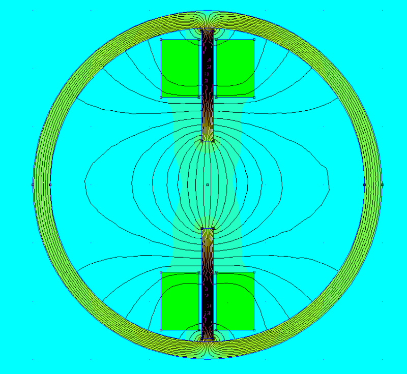
This is the basic setup:
30092016_154902_akvto9.png
 
This is a heat balance problem. The max current is where the rate of heat generation is greater than the rate of heat loss at a wire temperature of 200C. High power electromagnets often use copper tubing to carry current and cooling water. Immersing the coil in a fluid will also work. Without any cooling (no natural convection either), the allowable current would be zero. Wire ampacity tables are based on specific cooling conditions and temperature limits.
 
I see your point.
Forced air cooling would be a possibility. Liquid cooling is out of the question ..
The challenge would be to separate the 'hot spot' from the coil. Where the coil then would have air cooling.
I see an opportunity there ...
 
Since you posted the geometry, I thought it would be worth clarifying: is the outer circle a physical core or just a mathematical means to establish a boundary condition that simulates an unbounded geometry?

=====================================
(2B)+(2B)' ?
 
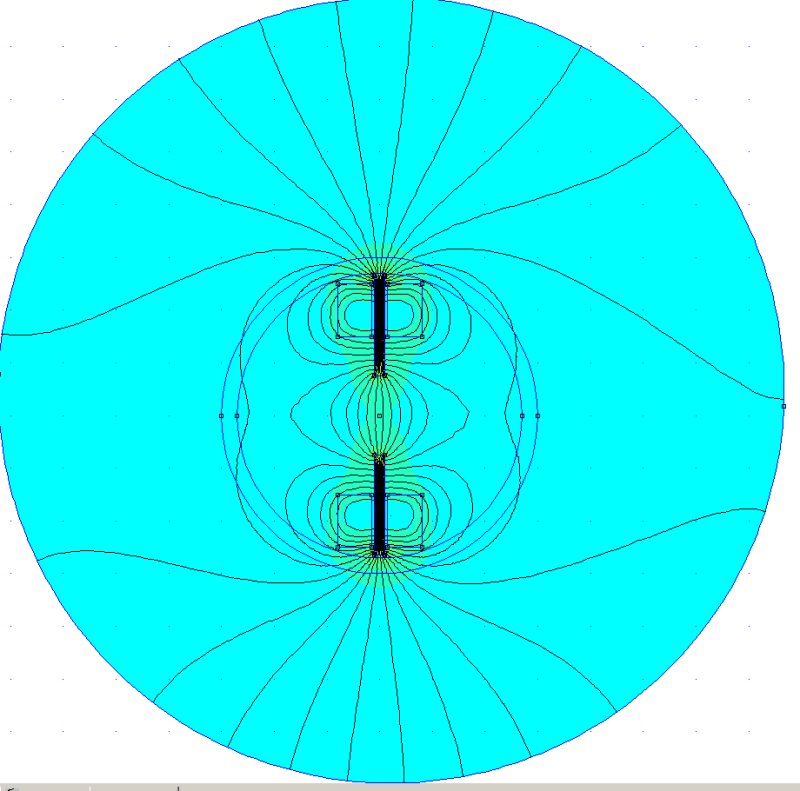
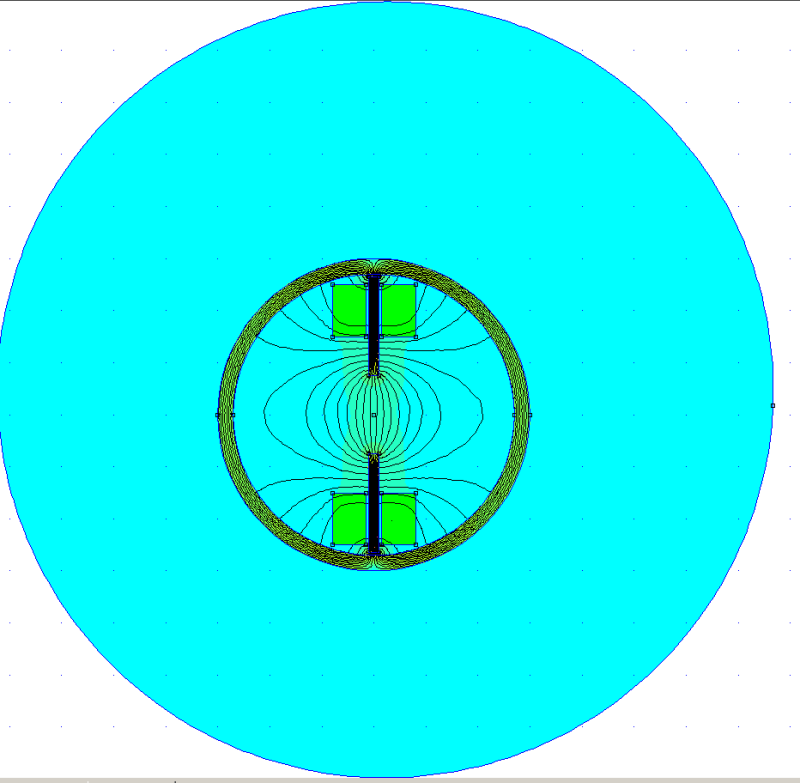
The outer circle is indeed a core. It is there to provide a 'return path' for the magnetic field, and to serve somewhat as a shield to isolate the setup of fields of neighbouring setups. There will be in fact 4 of these setups in a square-like configuration.
I am using a boundary but it is outside of this picture.
See pictures below that show the boundary, one with the circular core, and the other with the core 'removed'
06102016_163449_tuz4gd.png

06102016_163349_oi2bvo.png
 
ok thanks. If I had read your post carefully I would have figured it out but thanks again for clarifying.

=====================================
(2B)+(2B)' ?
 
what is the core material around? using mu-metal as the core for coils can decrease current applied, but also it is much easier to be saturated, and offers much less B than other core materials.
 
I was thinking of extending the mu-metal core so that I can move the coil further away from the hot spot, maybe even constructing some kind of heat-barrier between the coil and the hot spot.

I guess if this is an axisymmetric model, then the outer mu metal is spherical?
If it entirely encloses the coils airtight then the outer mu metal would be the coolest part of the geometry (since all heat is transferred outward to ambient through it). In that case you'd probably want to be as close to the mu metal as possible from the standpoint of giving the coil heat the easiest thermal path to escape (stagnant air between coil and mumetal is thermal insulation).

On the other hand if there is some good openings for circulation between inside and ambient then there might be improved circulation around the coil if you move it away from the outer shield.

I imagine there also may be a benefit in moving the coil to lower flux area since flux flowing across the windings may perturb the current distribution away from a uniform distribution such that the effective resistance and I^2*R is higher (similar to the way skin effect increases resistance when it makes the current distribution nonuniform). I don't know whether FEMM effectively models that or not.


=====================================
(2B)+(2B)' ?
 
@MagBen:
I haven't yet decided on the material of the core and the shield.
Since it is an AC coil (upto 330 Hz) I have to limit eddy-currents. So laminated mu-metal and ferrite are likely candidates.
Mu-metal gives me more freedom in the design, although for the cores I could use (standard?) ferrite rods.
 
@electricpete:
>I guess if this is an axisymmetric model, then the outer mu metal is spherical?
-- No, it is a planar model. The graphics above represent top views.
Probably, the top or the bottom will be open, allowing for some airflow.

I have limited space available. The diameter of the shield can be no larger than 60 mm (2.36 inch).
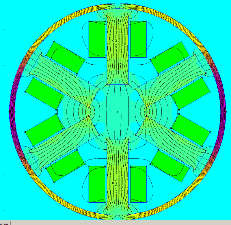
Furthermore, while the model shows only a single coilpair, in reality there will be 3 coilpairs, positioned at an angle of 120°.
Much like the coils of the stator of an asynchronous elektromotor.
See picture.
This very much limits the size of the coils. It is possible that I can't reach 50 mT, also because I have to limit the max current due to the high temperature.

That's why I am considering a different design. See my next post.

07102016_134855_njmlsj.png
 
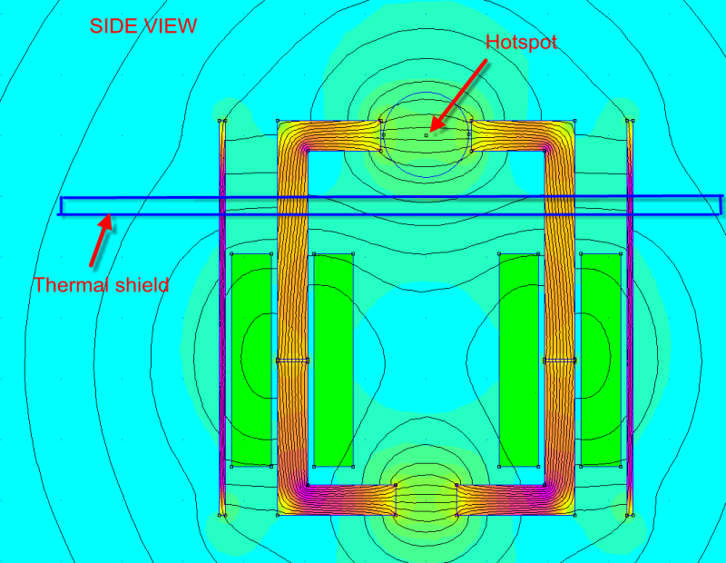
@electricpete:
This is my new design.
Note that this is a side view (planar model). So the coil axes are vertical.
With this design, I can make the coils bigger and also move them away from the 'hotspot' to a 'colder' place.
I could even incorporate some kind of thermal shield between the hotspot and the coils.
Forced air cooling on the coils is perhaps also an option.

07102016_135613_rehjcb.png
 
@hacksaw:
That is the value I have used so far in my simulations, but especially with the high temperature, I think this value might be a bit optimistic.
I found that for transformer design, the current density is typically kept between 2.5 to 4 Amps per sq. mm of wire cross section.
For a diameter of 0.25 mm and 4 A/mm2, this would result in about 200 mA max.
 
@Compositepro:
Which air gap do you mean? The one inside the coil, or the one below? Or the one above?
 
Status
Not open for further replies.

Part and Inventory Search

Sponsor