Eng-Tips is the largest engineering community on the Internet

Intelligent Work Forums for Engineering Professionals

  • Congratulations waross on being selected by the Tek-Tips community for having the most helpful posts in the forums last week. Way to Go!

Column Pile Bent Bracing

Status
Not open for further replies.

X-Wing

Civil/Environmental
Sep 26, 2012
71
0
0
PH
Good day!

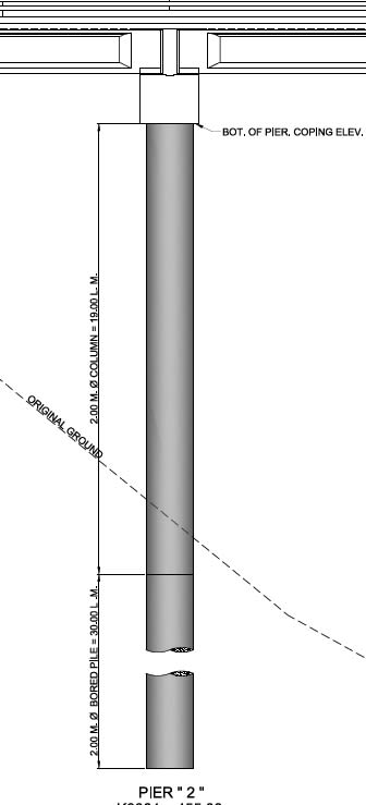
I would like to ask regarding the philosophy of multi-pile bent design of pier bridges. We are usually designing 2 column pier bent, with foundation resting either on bored piles or footing on piles. My design philosophy is to design those piers using additional moment as unbraced columns (sometimes up to 20 meters in height), instead of adding midheight column bracing.

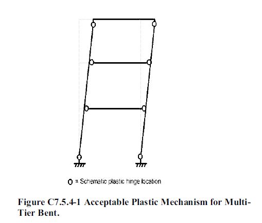
May I ask if there any harm in introducing midheight column bracing (concrete+steel section)? In my opinion is that instead of transferring loading from coping beam to/from column and foundation and introducing plastic hinging at the bottom/top, additional midheight concrete bracing will induce plastic moments that might cause failure at the column at midheight.

Please enlighten me regarding my design philosophy. Thanks!

Skywalker
 
Replies continue below

Recommended for you

I am trying to picture what you are describing.... Like adding a mid-height strut/beam between the columns?

Is your issue regarding slenderness concerns of the column for buckling? Even if you brace them to one another, they are not braced out of plane... In my experience, columns for bridges are typically really low on the P-M Interaction diagram anyway, that they are many times primarily bending elements as the compression can be around 0.10f'c. When you say coping beam, are you talking about hinging the bracing beam between the columns vs hinging the column itself?

See below. This antiquated bridge we widened several years back was the only one that I am familiar with in my area that used bracing between the bent columns. When we ran the pushover analysis, we did indeed use the plastic hinging of the bracing element as a source of dissipating the energy. We have designed other 100ft tall bridges from scratch that had no mid-height bracing.

Untitled_lkog70.png
 

Not sure i got the full problem.A sketch could be more helpful to get better responds... As far as i understand, you want to use multi tier frame bent with intermediate beam bracings..

This could an option but what is your plan to make sure that the plastic hinge formation will follow a sequence and latest hinging will be at bottom?..

This snap from AASHTO Guide Specifications for LRFD Seismic Bridge Design..

acceptable_hinging_mechanism_ssfpov.jpg
 
@BridgeSmith

Sorry I don't have definite picture of the Plan with bracing. Somewhat similar to STrctPono actually.

Here's another typical picture of another bridge, we simply add a column horizontal brace at mnidheight of the column

11_l7d2mu.jpg
22_mc15j7.jpg


@STrctPono

Yes horizontal bracing at the midheight same as your attached picture. What is the primary reason for including a bracing in your project? To control the drift since it's a widening project?

@HTURKAK and all

Do you have typical section oh how to make sure that the PH will occur on the bracing, not on the column?

Skywalker
 
For my project, the brace was already there. I tried figuring out the intent of the original designer but never was 100% sure what he was trying to achieve. That bridge was a bit of a work of art designed by a locally famous Engineer back in 1933. This was long before seismic analysis was ever even considered.

A couple of thoughts for your project...
1. Are you wanting to put in the bracing to control lateral drift or because of slenderness issues?
2. If this is because of lateral drift due to seismic analysis... Run an elastic analysis and apply a psuedo static load to your frame and measure the displacement (delta1). Then add the midheight brace in and check the displacement (delta2). Is the ratio of delta2/delta1 going to get you within your desired lateral displacement from your seismic analysis. This is just a preliminary check to see if adding the brace is even going to achieve what you are looking for.
3. Midheight brace should be detailed to ensure plastic hinging in the brace before the column. Obviously, regulating the section properties and % of flexural reinforcing is the way in which to do this. It will be an iterative process to arrive at the results you are looking for as it is a balancing act of satisfying the sequence of forming the hinges and still remaining within the target displacement. There are some elastic static analysis runs you can perform to preliminarily size your midheight brace within the ballpark prior to running the pushover analysis.
 
@STrctPono thanks for the response

It means that the designer back in the 1930's did designed the bridge with brace, way long before seismic analysis was considered. WOW!

1. Are you wanting to put in the bracing to control lateral drift or because of slenderness issues?
- Actually I am not considering using bracing in the design unless I need to control the lateral drift incase for widening?

2. If this is because of lateral drift due to seismic analysis... Run an elastic analysis and apply a psuedo static load to your frame and measure the displacement (delta1). Then add the midheight brace in and check the displacement (delta2). Is the ratio of delta2/delta1 going to get you within your desired lateral displacement from your seismic analysis. This is just a preliminary check to see if adding the brace is even going to achieve what you are looking for.
- Thanks for the advice, will do this

3. Midheight brace should be detailed to ensure plastic hinging in the brace before the column. Obviously, regulating the section properties and % of flexural reinforcing is the way in which to do this. It will be an iterative process to arrive at the results you are looking for as it is a balancing act of satisfying the sequence of forming the hinges and still remaining within the target displacement. There are some elastic static analysis runs you can perform to preliminarily size your midheight brace within the ballpark prior to running the pushover analysis.
- emphasis on the "regulating the section properties and flexural reinforcement", right on track this must be done to ensure PH in the bracing. One question is how do we ensure in the analysis that the connection will enduce PH in the bracing?


Skywalker
 
Young Skywalker,

To actually verify when and where it plastifies, you will need to run the response spectrum analysis and necessary moment curvature analysis of the different sections. From the RS analysis, you measure your displacements, and then run the non-linear pushover and match your displacements between the two. Plastic hinges may form along the way at different points within your frame.
 
Status
Not open for further replies.
Back
Top