Continue to Site

Eng-Tips is the largest engineering community on the Internet

Intelligent Work Forums for Engineering Professionals

  • Congratulations IDS on being selected by the Eng-Tips community for having the most helpful posts in the forums last week. Way to Go!

combined footing for truss-bracing element (compression and tension) 1

Status
Not open for further replies.

Gradstructengineer

Structural
Sep 13, 2022
10
Hi All,

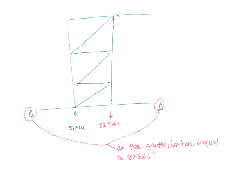
I have to design the footing for a truss brace. Please see attached image. Under wind loading the support reactions at the base of the footing are 82kN and -82.5kN. Do these forces cancel out each other with the total uplift load as 0.5kN or do I need to design a footing with a SW of 82.5kN to sustain the uplift forces of 82.5kN?

thanks in advance
 
 https://files.engineering.com/getfile.aspx?folder=3fddd72f-0d8a-4f17-a885-f52e4831679f&file=Brace_truss.JPG
Replies continue below

Recommended for you

You may not have net uplift on the combined footing but you will still need to design it for overturning which will involve similar concerns.

I'd start with generating a free body diagram of the footing if you haven't already. Post that here and we'll be happy to critique it for you.
 
the picture does not show any forces. please show a complete free body diagram with all member and reaction force vectors.
 
As others have said, you've missed the obvious first step which is to draw the freebody of your structure and foundation to resolve the forces
If you do, you'll find that your foundation has a shear on it combined with a moment (equal to shear x height of load)
There is no "uplift" per se - the reactions of 82.5kN up/down you're getting are just the analysis software decomposing the moment into point loads under the legs

If you draw the foundation and think about it, you have soil compression under the compression leg resisting one half of the moment couple
The other half, the tension or uplift side) is provided with concrete mass or something else
However, you don't need to provide 82.5kN of hold-down directly under the leg - you could, but it'd be really inefficient - you can do it by designing a ground beam that extends out past the tension side leg
I'm feeling friendly so I've done some example calcs based around some imaginary geometry to show what this could look like
I've simplified it dramatically as there are some other design considerations (e.g. where does the reaction sit within the soil itself? I've assumed all compression under the very edge) but it's enough to illustrate the principle

In your model you'd need 82.5kN of concrete to hold it down
In my imaginary example, using a ground beam, I've reduced that to 24kN/m3 * 0.5m * 0.4m * 11.7m = 56.2kN - a saving of about 30% by concrete weight
Hope this helps illustrate the approach that you need to take to solving these problems

Sorry it gets a bit cramped, I misjudged how many lines I needed...normally I'd be a lot neater. woops.

Screenshot_2022-10-12_101126_jd4cxa.png
 
Thank you KootK and SWComposites, thanks a lot Greenalleycat for taking the time to do a sample calculation.
Please see attached pdf of the free body diagram of the full structure. My understanding earlier was that I needed to have enough concrete equivalent to 82.5kN to resist uplift.
 
 https://files.engineering.com/getfile.aspx?folder=7e20eb0c-4c7f-455f-9309-531ce242bb87&file=truss_brace_foundation.pdf
Nice one mate, the sketch looks good
From a rough check of the maths it seems OK

A few things you'll need to work through if this is an actual design though
1) You've only got a 0.35m deep beam but your design moment is 82.5kN * 1.2m = 99kN.m - you may struggle to get that to work efficiently
Perhaps going to a 500mm wide beam that's 500mm deep could be more efficient? Play around with those options - I don't know what your constraints are so I can't help you there

2) As I mentioned in my previous post, I assumed that we were summing moments around the very edge of the footing, which you have now emulated
In reality, the compression isn't ultimately resisted by the concrete, it's resisted by the much softer and weaker soil underneath the concrete
So the compression block in the soil is what matters
Do you have geotechnical parameters for your soil bearing capacity etc? You'll need to account for this as it will reduce your lever arm and mean you need a bigger footing than currently sized
As a quick hint, I've chucked your footing into my spreadsheet I use for these designs and it doesn't work when accounting for this effect :)

As a visual example that may help, the below is a flanged wall I designed over a large footing
I modelled it up on springs to represent the soil and this is an output showing the force reactions that occur
You can see where all the greeny arrows are that there is compression reaction - makes sense as it's near the end of the wall
Then there is a large area with no reaction - this is where the concrete is actually uplifting so the soil doesn't support it
Eventually, near the left side, enough concrete has been picked up that the footing is no longer in net uplift

The key lesson here being: something may be stable for overturning but that doesn't mean it hasn't actually lifted off the ground!
You commonly here about this in footing design as "the middle third rule" or "the b/6 rule" which considers where the soil reaction is and whether any uplift is required for stability
Screenshot_2022-10-12_114944_k5x3u8.png


3) Just to make it clear - the connection of the tension leg to the concrete does need to handle the 82.5kN load (plus whatever shear is on it!) so make sure you do design for that force :)

4) Just to add to the piles of things to consider...in this example we have assumed that there is no significant GLOBAL axial demand on the frame
If this frame was say a fixed base portal frame leg instead, then we would have a global tension/compression (from frame action) and a moment at the portal base (from fixed base action)
In this case you need to consider both the moment and the tension/compression when doing your freebody / sum of moments on the footing
One of the effects you will identify with that is that an asymmetric system can become directionally critical i.e. you get different footing designs if your loading is -> vs <-

No stress about that misunderstanding, it's all part of the learning process!
Funnily enough I went through this exact type of problem with one of the guys in the office a few months ago
He thought he needed 50kN (2m x 1m x 1m!) of concrete under his portals
We modelled up a few ground beams to represent the as-drawn structure, and turns out everything resolves nicely without needing any extra concrete at all - just a few more bars

I distinctly recall two separate conversations that taught me the principles I've just shared with you, so we've all been there
If you want the super easy way to conceptualise the problem, think about the below - you can inherently see that an uplift of 82.5kN under the leg doesn't mean we need 82.5kN of concrete - just that the moments need to resolve
Screenshot_2022-10-12_113938_nrr9na.png
 
Don't forget that the forces might be reversible and this could impact the stability and strength of foundation calculations. Remember forces are vectors, they have magnitude, direction, and point of application. In this case the FBD clearly shows you that the forces don't have the same point of application so they do not 'cancel' out. Instead the foundation element is used to resolve the forces via bending, shear, and bearing on the soil.
 
Status
Not open for further replies.

Part and Inventory Search

Sponsor