Eng-Tips is the largest engineering community on the Internet

Intelligent Work Forums for Engineering Professionals

combined stresses on pipe clamp 3

Status
Not open for further replies.

vgengineer66

Mechanical
Jul 25, 2014
18
0
0
IN
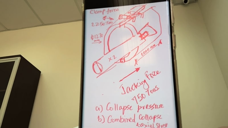
I am trying to calculate the combined stresses on a pipe clamp.
2 forces acting on it.
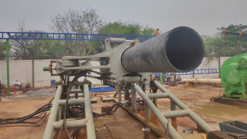
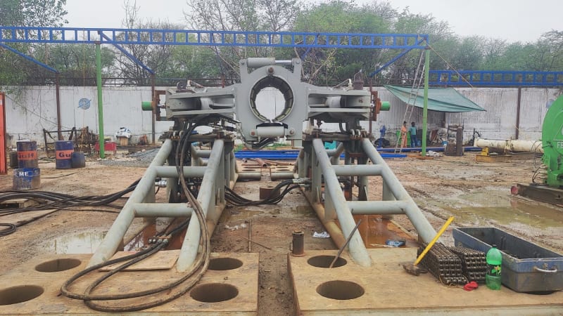
a) the clamp is in 2 halves , the 2 halves connected with 10 hyd cylinders on top (12'o clock) exerting a closing force of 2000 tons
b) another 2 cylinders connected at 9 o clock and 3 o clock exerting axial force on 750 tons.
c) What wold be the collapse pressure of this clamp
The clamp is 50 inch OD, Yield Stress of Pipe is 60,000 psi and wall thickness is 0.7 inch, lenght of clamp is 80 inches
 
Replies continue below

Recommended for you

Hi

Please post a sketch or picture of the situation.

“Do not worry about your problems with mathematics, I assure you mine are far greater.” Albert Einstein
 
omik8gmxhkaiycvglmhs.jpg
 
so I have say 10 Hyd cylinders on the top of the clamp with a TOTAL clamping force of 2300 tons
and I have 2 cylinders on either side with a total Pushing force of 750 tons.

My clamp has an ID of 1.27 meters and a length of 2 m.
My clamp if clamping a pipe of :
OD 1.27 m
wall thickness of 17 mm
Yield strength of pipe is 4150 kg/cm2

Need to calculate the
a) Collapse pressure on pipe
b) Combined Collapse and Axial stress on pipe (the clamping and the pushing)
 
Hi vgengineer66

Looking at the sketch you provide I assume there is a hinge at the base of the clamp??. When the clamp is in operation is there a gap at the top of the clamp such that the clamp faces are not touching? This being the case the clamp will only clamp on the pipe in one spot and will not be an even pressure around the pipe, let’s say the clamp acts on the midpoint of the pipe therefore if you take moments about the hinge of the clamp then the clamping force on the pipe mid section will be 4000lbs. I haven’t got any formula for pipes or pipe clamps under point loading to hand but can you confirm my assumptions that I have made so far.

“Do not worry about your problems with mathematics, I assure you mine are far greater.” Albert Einstein
 
The clamp will grip the pipe evenly. all 360 degrees. The hinge is outside of the clamp and the inside is flush with pipe.

The pipe clamping on top, with hinge being diametrically opposite, the moment will be f x d, f = 2250 tons and d is 1.27 m
the thrust cylinder is right in center (750 tons) and along the axis, so i believe the moment from this force may not be there.

Rgds
 
Collapse pressure of the clamp?

What collapse pressure? The thing is open at both ends?

Pressure on the pipe is clamping force divided by area of the clamp no? So 2.8Mpa or 28 bar equivalent? There are collapse formula in offshore pipe codes.
17mm thick on 1.27m is a D/t of 70. Sounds rather thin to me.

But clamps are not quite the same as water pressure so not sure if this is the right way to think about. Might need an FEA analysis. Or a structural man used to clamping pipes / structural pipe on oil rigs and similar.

Remember - More details = better answers
Also: If you get a response it's polite to respond to it.
 
Hi

I very much doubt that it will grip evenly all the way round 360 degrees, if your clamp is going to work then when the clamp is actuated there should be a gap between the clamp faces at the top.
Do you have a proper drawing showing the pipe clamped in the jaws of the clamp? If the clamp faces at the top have no gap they won’t be clamping the pipe in my opinion.

“Do not worry about your problems with mathematics, I assure you mine are far greater.” Albert Einstein
 
vdengineer66...

I agree with the comments of LittleInch ... However, your incomplete description of the problem compounded by your limited word usage is causing difficulties and most delays of any help from eng-tips.

Are you trying to "crimp" this massive pipe and achieve a pressure-tight seal ? .... Who knows ???... I can't tell..

Can you get someone to help you explain "collapse pressure of the clamp" .... I don't understand this either

It should be pointed out that you have decided to clamp a very thin walled piping system (Do/t = 1270/17 =74)

This, IMHO, is the primary source of your problem...

You state:

"so I have say 10 Hyd cylinders on the top of the clamp with a TOTAL clamping force of 2300 tons
and I have 2 cylinders on either side with a total Pushing force of 750 tons"

Where do these numbers come from ?.... are they just some RA estimate or an MBA opinion ? ....

Where are your calculatons ?

MJCronin
Sr. Process Engineer
 
I think vdengineer is interested in this HDD push pull system. also has an axial force of 750 tons!

See also the attachment for information.

So I think he or she is interested to know if their pipe will collapse. I would just ask the contractor and check his calculations.


Screenshot_2023-06-21_164957_cebbp5.jpg


Remember - More details = better answers
Also: If you get a response it's polite to respond to it.
 
Let the guessing games continue !!!

With very poor word skills, a reluctance to say very much, as well as horrendous drawing abilities, this should only take twenty or thirty more questions !!!

Again, what is meant by "collapse pressure of the clamp" ??.... I don't understand this either

Here is a wild idea .... If indeed, the OP was interested in a "HDD push pull system".... he could say so !!!

Naaaaaaaaaa !!! ..... He has given up on this thread and gone on to other things...


I am going to urge the eng-tips admin to close this thread


MJCronin
Sr. Process Engineer
 
The clamping units seems just slight more sophisticated than the OP's sketch.


The clamping plates of the unit that are lined with special rubber have a sufficiently large contact surface to the pipe. In this way, they keep the contact pressure and the shear stress applied on the pipe low.
 
Respected Engineers,

I am overwhelmed by your responses.
pl consider the following for understanding:
a) This is my first ever post on Eng Tips and I shared a part of problem that I was stuck on.
b) I do respond fairly quickly, the difference is the time zone, I am in India and we are 12 hr diff time zone. So all your responses happened in my night time, which I saw today morning at 6 am.

I shall share the full problem and hopefully will get a better solutions from the forum.

Thanks to all for your very valuable posts....
Here i go with my calcs and some better drawings...

Regards,
Vipin Gupta
 
 https://files.engineering.com/getfile.aspx?folder=c49fe5fe-c954-4f96-a720-16edff3af763&file=20_inch_thruster_Side_Tilted_with_pipe.jpeg
this is the calc done my me for collapse pressure transferred from clamp to the pipe
excel sheet attached.
this calc passes the 20 inch pipe for 500 tons, but fails on the 50 inch pipe. But from what I was told by Harrenknecht, they are able to safely clamp the 56 inch pipe, X-52 with a wall thickness of 16 mm to a push load of 750 tons and clamp force of 2250 tons.

 
 https://files.engineering.com/getfile.aspx?folder=a70e8cb8-02b2-4f4c-aec1-667af381b127&file=clamp_pr_calcs_Rev_1_June_20,_2023.xlsx
Now to summarise:

Yes, we are designing and fabricating a Pipe Thruster for HDD applications. We have done this for 3 pipes of 20" 24" and 36" and used them successfully.
now we need to push a 50 inch pipe with a low w.t. of 0.7" where the d/t ratio is 71. Besides we need to design for a load of 750 Tons Push.
with a cof of 0.3 , we shall need a clamp force of 2250 tons.

I am afraid that will crumble/collapse/crush the pipe and need help.

Trust, with the photos and the calcs and propoer autocad drawing, I am able to make it clear
 
Been working on the External collapse pressure of pipe and we get 2 equations with vastly different results.
a) Lames equation for d/t<15
Pyp = 2 x Yp (d/t-1)/(d/t)^2
Substituting,
Yp @ 60,000 psi
D/t @ 74 (50"/0.7")
= 1599.7 psi

b) Elastic collapse for d/t > 25
Pe=46.95 x 10^6/(d/t x (d/t-1)^2
= 119 psi

In my case the elastic collapse seems reasonable, but then it does not address the YS of the pipe.
 
Status
Not open for further replies.
Back
Top