Kristina Sornikova
Aerospace
Dear All,
Sorry for this basic question. I learn in past Mc/I only applicable to principal axes.
But this professor use neutral axis, which is at angle to principal axes to find max and min point, but use principal axes for stress?
Here is link:
So my question: If use neutral axis, I get same point for one end 'B'.
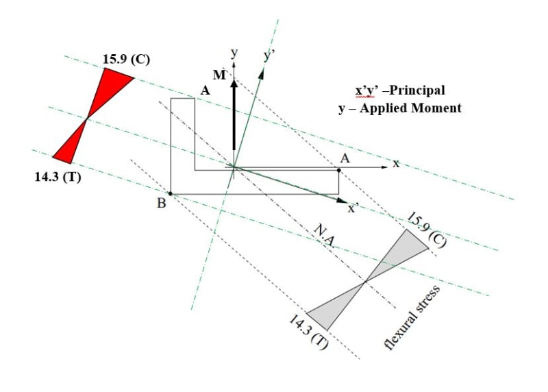
But if use principal, I get different point for 'A'? Which is correct? See image below.
When you do section bending + axial (assume shear zero) check of any unsymmetric section, you use principal or neutral for extreme fiber and bending stress?
I know neutral means no axial stress, and principal means no Ixy, meaning no twisting if applied moment is not aligned with principal.
I also not getting same stress distribution (where is tension where is compression) if use principal compared to neutral using Mc/I.
May be I am doing wrong. See image below, bit confusing. What you think?
Sorry for this basic question. I learn in past Mc/I only applicable to principal axes.
But this professor use neutral axis, which is at angle to principal axes to find max and min point, but use principal axes for stress?
Here is link:
So my question: If use neutral axis, I get same point for one end 'B'.
But if use principal, I get different point for 'A'? Which is correct? See image below.
When you do section bending + axial (assume shear zero) check of any unsymmetric section, you use principal or neutral for extreme fiber and bending stress?
I know neutral means no axial stress, and principal means no Ixy, meaning no twisting if applied moment is not aligned with principal.
I also not getting same stress distribution (where is tension where is compression) if use principal compared to neutral using Mc/I.
May be I am doing wrong. See image below, bit confusing. What you think?