Continue to Site

Eng-Tips is the largest engineering community on the Internet

Intelligent Work Forums for Engineering Professionals

  • Congratulations KootK on being selected by the Eng-Tips community for having the most helpful posts in the forums last week. Way to Go!

Unsymmetric Section Neural Axis Vs Principal Axes Maximum and Minimum Stresses

Status
Not open for further replies.

Kristina Sornikova

Aerospace
Nov 8, 2016
87
Dear All,

Sorry for this basic question. I learn in past Mc/I only applicable to principal axes.
But this professor use neutral axis, which is at angle to principal axes to find max and min point, but use principal axes for stress?
Here is link:

So my question: If use neutral axis, I get same point for one end 'B'.
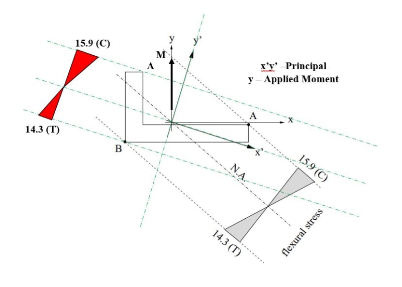
But if use principal, I get different point for 'A'? Which is correct? See image below.
When you do section bending + axial (assume shear zero) check of any unsymmetric section, you use principal or neutral for extreme fiber and bending stress?
I know neutral means no axial stress, and principal means no Ixy, meaning no twisting if applied moment is not aligned with principal.
I also not getting same stress distribution (where is tension where is compression) if use principal compared to neutral using Mc/I.
May be I am doing wrong. See image below, bit confusing. What you think?
Capture_ctcake.jpg
 
Replies continue below

Recommended for you

I tried your way, load the end of the angle going right at the face CG. Now the angle twists the way we think.

Capture_ny50uh.png
 
I haven't got a spreadsheet that does all the analysis that you're after. I can however suggest having a look at Niu, it covers non-symmetric sections for both bending and direct shear, using the Ixx, Iyy and Ixy method, in an x,y coordinate system. For torsion, there is a section in Roark that includes an L section case, it identifies the points about the profile where maximum torsional shear stress occurs.
 
AbbottAerospace ?

"Hoffen wir mal, dass alles gut geht !"
General Paulus, Nov 1942, outside Stalingrad after the launch of Operation Uranus.
 
If you decide to use the Niu method for direct shear stress (uses Ixx, Iyy and Ixy), part of the non-symmetric section calculation requires the 1st moment of areas to be calculated. I came across this file I've attachment, which I remember doing many many years ago. It calculates the 1st MOA for an L section, about the axes at the centroid. You will have point(s) of maximum direct shear (note, shears due to two direct forces in equation), in addition to the max. torsional shear stress points. You will need the corresponding bending, axial, direct and torsional shears at each max. point. Hope it gives you some ideas.
 
 https://files.engineering.com/getfile.aspx?folder=a5af2e68-b8aa-4806-a1b4-7d8b6e45e276&file=L_Section_1st_MOA.pdf
I've tweaked the 1st attachment I posted, it can now calculate bending stresses, shear flows due to direct forces and axial stress at key points about the L section profile. Torsional shear stress can be calculated using the Roark method, which identifies the locations of the max torsional shear stresses by the inscribed circle contact points with the L section profile at the elbow. These points can be included in the attachment L section, to calculate the other three stress components. There may be other easier ways to calculate the component stresses for the unsymmetric L section by hand, or there's always FEA. Although the attachment hasn't been checked and was created for personal interest only, it may be helpful and give some ideas.
 
 https://files.engineering.com/getfile.aspx?folder=98f3dba1-65c5-453f-86f0-77338b498093&file=L_Section_Bnd-Shr-Axl_Example.pdf
Status
Not open for further replies.

Part and Inventory Search

Sponsor