Continue to Site

Eng-Tips is the largest engineering community on the Internet

Intelligent Work Forums for Engineering Professionals

  • Congratulations waross on being selected by the Eng-Tips community for having the most helpful posts in the forums last week. Way to Go!

Combined Timber and Microlam Beam Load Sharing

Lutfi

Structural
Oct 20, 2002
1,035
It has been a long while since I have been in this forum. Hello everyone.

I want to pick everyone’s brain here.

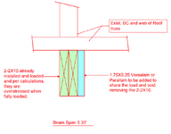
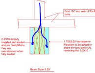
I have been called, of course after the fact, to evaluate a situation where a contractor has already installed a beam, 9.33’ span made up from SYP number 2. The beam is supporting 5 roof trusses, and it is already loaded. See the attached simple and NTS section.

The contractor and the owner are not for removing and replacing the already installed 2-2X10.

My approach is to add an Microlam on one side or both sides of the beam. I know the conservative approach is to assume the Microlam will carry all the entire load. This would be the easy way out. However, being an engineer, I want a logical way that I can use with the assumption that both beams are sharing the load proportionally based on their stiffness. So, I can apply prorated load to each one.

My question is, how to come up with a logical prorating percentage?

Please no comment to chastise the contactor nor the owner.
 

Attachments

  • 2-2X10 and LVL Concept-Flattened.pdf
    20.4 KB · Views: 25
Replies continue below

Recommended for you

1735058388141.png
I know the conservative approach is to assume the Microlam will carry all the entire load. This would be the easy way out.
This is probably what I would do. There's nothing wrong with taking the easy way out IMO. I know this isn't really your question, but to elaborate, I would consider using LVLs along both sides and a through bolted connection. This would result in a nice symmetric section that's well connected.

Anyway, on to your actual question:
I want a logical way that I can use with the assumption that both beams are sharing the load proportionally based on their stiffness.
I feel like you just answered your own question. Why not calculate the stiffness, EI, for the 2-2x10, then the LVL, and use those values to determine how the load would be shared?

Along the same lines, you could scale the width of the LVL proportionate to the moduli of elasticity: E_LVL / E_SYP. So, if E_LVL is 2,800,000 psi and E_SYP is 1,400,000 psi, for example, you could say that the 1.75" wide LVL has equivalent stiffness to a 3.5" wide SYP beam (1.75 * 2,800,000 / 1,400,000). Based on these rough numbers, and assuming there's a load path from the applied load to the new LVL piece, you could conclude that the 1.75" LVL (3.5" SYP equivalent) is a little bit stiffer than the 3" wide SYP beam.

Hopefully that helps.
 
View attachment 2724

This is probably what I would do. There's nothing wrong with taking the easy way out IMO. I know this isn't really your question, but to elaborate, I would consider using LVLs along both sides and a through bolted connection. This would result in a nice symmetric section that's well connected.

Anyway, on to your actual question:

I feel like you just answered your own question. Why not calculate the stiffness, EI, for the 2-2x10, then the LVL, and use those values to determine how the load would be shared?

Along the same lines, you could scale the width of the LVL proportionate to the moduli of elasticity: E_LVL / E_SYP. So, if E_LVL is 2,800,000 psi and E_SYP is 1,400,000 psi, for example, you could say that the 1.75" wide LVL has equivalent stiffness to a 3.5" wide SYP beam (1.75 * 2,800,000 / 1,400,000). Based on these rough numbers, and assuming there's a load path from the applied load to the new LVL piece, you could conclude that the 1.75" LVL (3.5" SYP equivalent) is a little bit stiffer than the 3" wide SYP beam.

Hopefully that helps.
Thanks for the response. Your thinking and approach lines up 100% with mine.

Cheers!
 
The added LVL is not going to pick up the existing dead load, unless you somehow unload the existing beam. So the load sharing will only be for the live load.
 
The added LVL is not going to pick up the existing dead load, unless you somehow unload the existing beam.
That's a good point. You could also jack up the existing beam before sistering the new LVL if this is a concern.
 
The added LVL is not going to pick up the existing dead load, unless you somehow unload the existing beam. So the load sharing will only be for the live load.
You are correct. The plan to consider loading the LVL for the live and wind loads only. It s to risky, I think, to jack the beam and alleviate the dead load.
 
Sounds unnecessarily convoluted. It's almost some kind of bridge sequencing calc. It also looks like the trusses are being used "implicitly" to brace the beam. That could use some attention. And since there's a roof involved may as well mention uplift where the beam isn't going to be meaningfully braced on the bottom.

At any rate, to contribute in a more positive fashion, the preload (dead load) won't transfer out unless you shore it first, if you don't, the connections have to be scaled for the load that your stiffness analysis says the LVL "wants" to take, or you design a sufficient transfer that's less than this with your connections to produce a safe condition for a lesser load.

I would not try to connect them for composite action via shear flow or something, just vertical load. Or to stabilize the LVL against the (2) 2x12s for bending.

There's also potentially the argument that the truss is going to force load transfer without a specific connection as the (2) 2x12 will deflect downward when (over) loaded and force bearing on the LVLs, provided the truss doesn't crush. Bearing enhancer?

Deflection will be a bit fuzzy, but if they enclose it late in the process it may not crack down the road.
 
My thoughts about this:
a) I like simple and approximate solutions rather than exact solutions. I'm not doing a PhD thesis for every small project. Not worth my time, not worth the client's money.

b) Simple Option #1, just share the total load between the two beams based on their relative stiffnesses. Simple, but not 100% accurate based on the fact that there is already load in the existing beam. Slight modification where you just share any new load between the beams. Maybe event split dead load into existing and future (super-imposed).

c) Simple Option #2: You could calculate the total capacity of the two beams and assume that any existing load will get "shared" as the beams approach failure.... A friend of mine (who is the best engineer I know) made me do this on a project I worked on for him because Option #1 was putting SLIGHTLY too much load in the new LVL. I don't think this is "technically" correct. KootK was actually the one who pointed this out to me. Tension failure in a wood beam is not all that ductile and load is probably not as shared like this near failure. That being said, I don't think this method is really all that dangerous either. As long as the method #1 is close to working.

My point being that if it calcs out on paper using a method you know isn't 100% correct, that's okay..... As long as your engineering judgment tells you that you're comfortable with the design.
 
Great points above. I've often used an approach similar to "Simple Option #2." If each beam, analyzed independently, were to "fail" by a factor less than 2, I don't think I'd lose any sleep over that solution, at least not for a conventionally framed wood floor. I can't imagine one beam failing independent of the other.
 
That simple option 2 doesn't sound like it's based on well established principles of mechanics.

I'm dismayed how KootK hasn't engaged on this one, for the record.
 
Typically I would take route #1, where I distribute load based upon stiffness, with a sufficient connection pattern to ensure appropriate load sharing. The issue with this, however, is the nominal design value for MOE is based upon a rolling average, and is not necessarily representative of the individual piece. See Appendix F in the NDS, for MOE of visually graded sawn lumber, the coefficient of variation is 25%, which is pretty darn high. Without performing some non-destructive testing on the material already installed, you're going to have some difficult determining the actual stiffness of the installed member, as well as the actual stiffness of the supplement LVL, which will cause difficulty in efficiently applying load to each individual lamination based upon a stiffness method.

If you are concerned, I might suggest sizing the LVL to take the load itself, and treat the 2x_ material only as a lateral torsional buckling restraint. In the OP, it was mentioned that the beam was recently installed, perhaps there is not much DL deflection in the member at this time, and you can develop a way to ignore that part of the analysis.
 
lexpatrie: That simple option 2 doesn't sound like it's based on well established principles of mechanics.
Well, it's not. The idea is more like.... there is load sharing between the two beams as one of them begins to yield / fail. So, something more applicable to a ductile failure mode. That's pretty much what KootK said in the previous thread to me.

Then he pointed me to a video showing a wood beam failing in tension bending (IIRC). For wood, compression failures are more ductile than tension ones. That being said, I take little issue with what my boss at the time wanted me to do (the option #2)... because the LVL was ALMOST strong enough to take the load based solely on the relatively stiffnesses of the two members. And, I had also analyzed it another way (existing load all going into existing beam and the new loads being split by relative stiffness) where the existing beam ALMOST made it and the LVL..... Ergo, you could hypothesize that the real behavior must be somewhere between the two methods and accept method 2 based on engineering judgement.
 
The calcs may show the existing 2xs fail. But have the actually failed ?

If the beam safely supports the dead load the. Isn't the additional ply for increased loading anyway? If it's okay where it is and you don't want it to go down more maybe jacking it up is not necessary.

Most of the time If I'm trying to avoid the PhD thesis of relatively stiffness I would do one of the following.
1 - design the new ply to carry the entire load. SCL is so much stiffer/stronger that a single ply often works for this calc.
2 - ignore the benefits of item 1 and assume it's another ply of the same type of sawn lumber.

I had a project where I called for this type of reinforcing on a bunch of old roofs. I poured over the relative stiffness and load sharing of the sawn lumber to the SCL. Pretty quickly you see a trend where the stiffness of the lvl takes the lion share of the load. Imho it's not worth thinking about too much for a single 9 ft header.
 
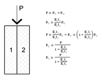
I'm not sure where I got this in the past, and it may not be useful to OP, but it is relevant to the discussion so I will drop it in. (This only works out where the member depths are the same or very close to, OR when the members share the same neutral axis).

Beam Load Proportioning.png
 
The calcs may show the existing 2xs fail. But have the actually failed ?

If the beam safely supports the dead load the. Isn't the additional ply for increased loading anyway? If it's okay where it is and you don't want it to go down more maybe jacking it up is not necessary.

Most of the time If I'm trying to avoid the PhD thesis of relatively stiffness I would do one of the following.
1 - design the new ply to carry the entire load. SCL is so much stiffer/stronger that a single ply often works for this calc.
2 - ignore the benefits of item 1 and assume it's another ply of the same type of sawn lumber.

I had a project where I called for this type of reinforcing on a bunch of old roofs. I poured over the relative stiffness and load sharing of the sawn lumber to the SCL. Pretty quickly you see a trend where the stiffness of the lvl takes the lion share of the load. Imho it's not worth thinking about too much for a single 9 ft header.
I do the same. LVL/PSL's are so much stronger than the 2x's I wouldn't worry about utilizing the existing 2-2x in this case. I'd run a super fast check to make sure it can take just the existing dead load, but design the new LVL (ideally one on each side) to take all the loads.
 
add an Microlam on one side or both sides of the beam

I would do both sides of the existing beam, all day long, if that is possible.

All load getting to the single LVL through the fasteners gets there through a path that induces torsion in the assembly. The double LVL rectifies that and simplifies many things in what is, as you can see from this conversation, a very complex problem if you think about it hard enough. Existing dead load, creep in the existing and the new, uncertainties associated with jacking, tolerances in the moduli of the existing and new members...

It can be a tough thing to come up with a rational method of keeping the existing beams from failing in flexural tension without introducing a lot of CYA conservatism. If the existing beams fail in flexural tension, then it is very much in doubt that the fasteners directing the load over to the LVL through those existing beams will still function as assumed. A flexural tension failure in wood is kind of a violent thing. So it pays to throw as much stiffness and symmetry at the situation as practical and, hopefully, keep the existing members intact.

I agree that the truss bottom chord can probably redirect load over to the LVL to a degree. That doesn't change my preference though. And, if you're adding the LVL to an already deflected beam sans jacking, it may not be practical to try to get the new LVL snug up to the underside of the truss bottom chords anyhow. In which case all of the load going to the LVL gets there via the fasteners.

Numbers schmumbers... all good engineering starts with good fundamental decisions. And, if you have the option, I feel that a two sided sistering would be a great fundamental decision.

c01.JPG
 

Part and Inventory Search

Sponsor