Eng-Tips is the largest engineering community on the Internet

Intelligent Work Forums for Engineering Professionals

  • Congratulations waross on being selected by the Eng-Tips community for having the most helpful posts in the forums last week. Way to Go!

Compensation issue 3

Status
Not open for further replies.

Mandalore

Mechanical
Sep 27, 2017
8
PL
Hello everyone.
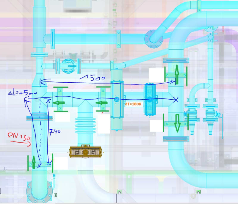
I encountered a problem related to pipeline compensation as you can see in the attached picture. This is an installation project from an external contractor. The green arrows represent the sliding supports. Pipe size 6 in. Temperature rise 180 K. Stainless steel tube. Do I understand correctly that a pipeline sized 1500mm will extend approximately 5mm in the direction shown (blue arrow) and will act on the perpendicular pipe 740mm from the sliding support (probably leading to failure)?
I kindly ask for an explanation. Unfortunately, I am completely unfamiliar with compensation topics. Sorry for the poor paint sketch.

pipeline_issue_mbrm1z.jpg


Regards
 
Replies continue below

Recommended for you

Correct. I estimated somewhat lower expansion, but yes, that is basically correct.

The pipe will expand in length. It will expand in the direction of least resistance. That is probably going to be in the direction of your smaller pipe diameters, the reducer and tee will probably get a pretty good twist, and could fail there, as the DN150 is considerably the stronger side of that connection.

Your 1500mm length of pipe should go up (assuming that's a plan dwg) at one tee, run horizontally for 1500mm then come down to the other tee. That will add a lot of flexibility into an otherwise very rigid configuration.

Einstein gave the same test to students every year. When asked why he would do something like that, "Because the answers had changed."
 
The thermal expansion of the 1500 mm segment will be approximately 5 mm as stated. In english units (sorry but I use english units)the axial thermal expansion of the 1500 mm pipe is:

(A)(L)dT = (9 x .000001)(3.28 x 1.5 x 12)(1.8 x 180) = 0.172 inches = 4.37 mm

A= Coefficient of thermal Expansion for stainless steel= 9 x 10[sup]-6[/sup] in/in/degF
L= pipe lenght inches
dT = Pipe temperature differential degrees fahrenheit

If the 1500 mm pipe was restricted from moving in the oppossite direction to the right then yes it would move toward the left as shown bending the 740 mm pipe leg as shown while also bending the connecting smaller pipe above the connection point in a similar way although the smaller pipe above don't have any restrictions like the sliding support.

Howeveer there are a lot of things to consider here. Do the sliding supports have any gaps between the attachment to the pipe and the structural member that would allow it to slide some of the 5 mm displacemnt. Usually a sliding support will be installed with gaps that allow some horizontal movement before contact is made and expansion is restricted. Usually a gap of 1/8" to 1/4" is typically used. This goes for the sliding supports on the opposite side of the 1500 mm pipe. Therefore if there are sufficient gaps at the supports then the only restriction for themal expansion perpendicular to the 1500 mm pipe would be from the connected piping but not from the supports.

Since there is a lot of interconnecting piping there will be a lot of restriction to the 1500 mm pipe from expansing and also a lot of restriction to all the interconnecting piping from expanding in all directions depending on how long the segments of piping are and how they are restricted from thermal expansing by the supports (where are anchors, guides and stops placed?). for instance the 6" piping at the right of the 1500 mm pipe is expanding thermally in the same direction as the 1500 mm pipe so it the resulting expansion into the 740 mm pipe could be a lot more if there are gaps at the sliding supports on the right side. In other words you need to look as all pipe expansion into any particular pipe leg that will be in bending stress.

Since 6" line and 180 K temperature difference a formal computer stress analysis such as Caesar II should be performed to dedtermine if the pipe has adequate flexibility and support. It can be done by hand but it gets too complicated to keep track of all the expansion of all runs of pipe.
 
Mangalore.

This is a piping stress analysis issue. You need to get a piping stress engineer involved and run a stress analysis program of your choice. This could be not an issue, it could be a big issue.

5mm is not a lot of expansion.

Remember - More details = better answers
Also: If you get a response it's polite to respond to it.
 
I agree with Snickster and Littleinch ...

Competent Piping design is not a matter of simply drawing the system in CAD.... Detailed stress analysis and pipe support design for some systems is often required... and often resisted by Project Management

Oh, small suggestion here .... I would refer to "piping system thermal flexibility" ... rather than "compensation"

Piping compensation sounds like he system is somehow on the company payroll

MJCronin
Sr. Process Engineer
 
Status
Not open for further replies.

Part and Inventory Search

Sponsor

Back
Top