Continue to Site

Eng-Tips is the largest engineering community on the Internet

Intelligent Work Forums for Engineering Professionals

  • Congratulations KootK on being selected by the Eng-Tips community for having the most helpful posts in the forums last week. Way to Go!

Composite Arch Construction Stage Analysis

Status
Not open for further replies.

netsonicyxf

Structural
Feb 19, 2010
49
The arch has 96m in span and 19.2m in rise. It has pin support at both ends and is made of steel and concrete.
It has 3 Construction Stages
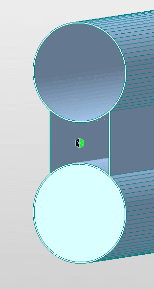
1. field installation of steel tube
1_nqee1p.png

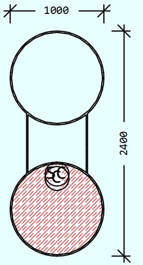
2. put concrete in the bottom steel tube
1_obwmny.png

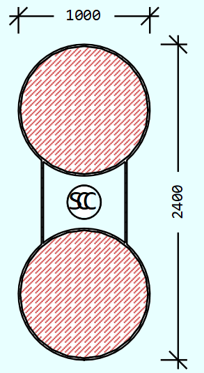
3. put concrete in the top steel tube
1_spmn84.png


We use Midas Civil, RM Bridge (TDV) and Sofistik to do the construction stage analysis
We will consider time effects, such as creep, shrinkage and E module increasing with time in the furture. But for now, the model is under self-weight only, no time effects.
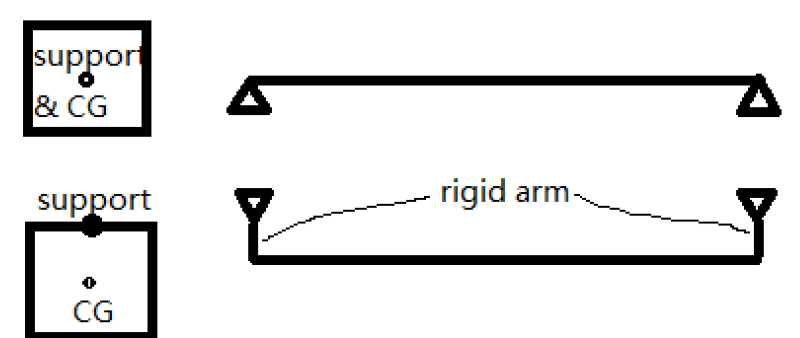
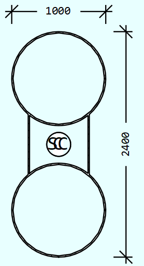
The boundary conditions are the same for all 3 softwares in all 3 stages, the support is at geometry center of the whole steel tube as shown in the stage 1.
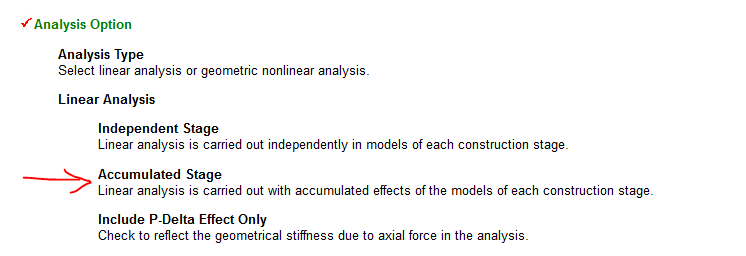
For Midas, we use NonLinear analysis considering Accumulated Stage
Geometric nonlinear analysis is carried out with accumulated effects of the models of each construction stage. This option is used for the forward analysis of a cable stayed bridge considering large displacement.
For RM Bridge, we use “Accumulate Stiffness (Stage) Analysis”
The internal force state (normal forces) of previous construction stages is considered in the p-delta effect calculation. The relevant internal force state must be stored in the specified summation load case.
For Sofistik, we use CSM(Construction Stage Module) Line (Linear analysis) and CSM → TH3 (3rd order geometry nonlinear), both gives very similar results

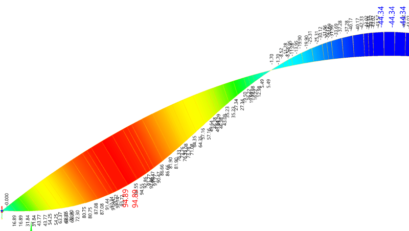
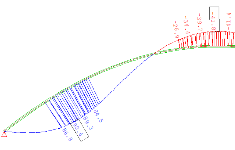
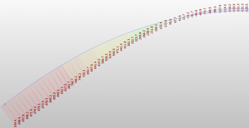
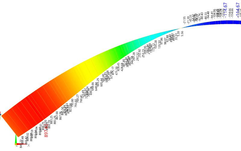
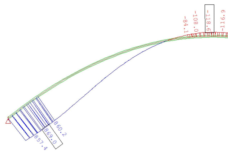
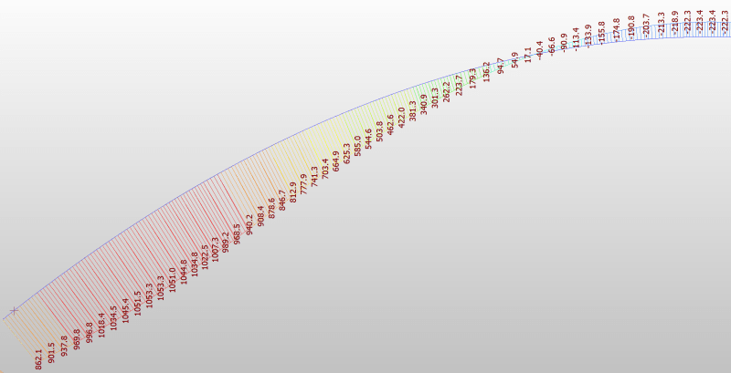
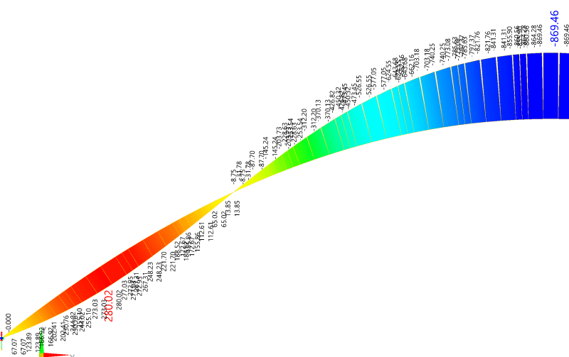
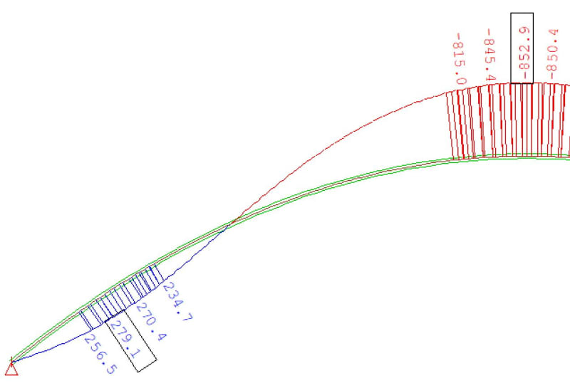
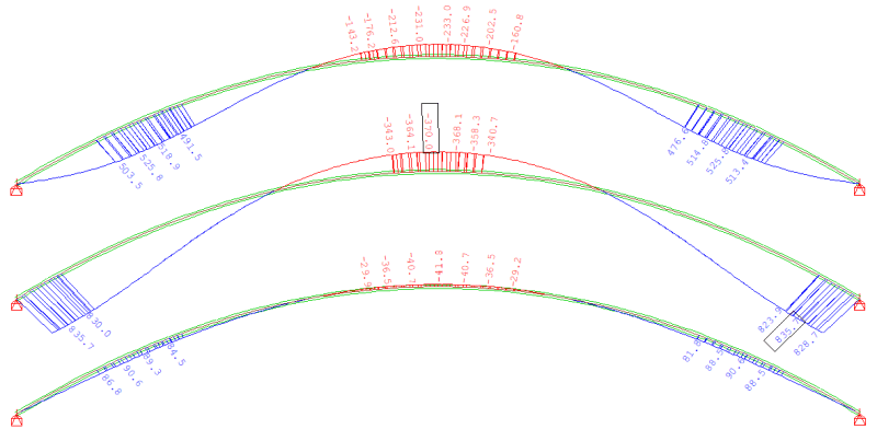
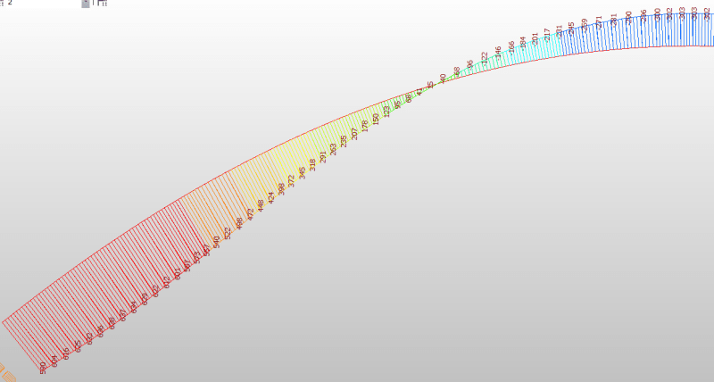
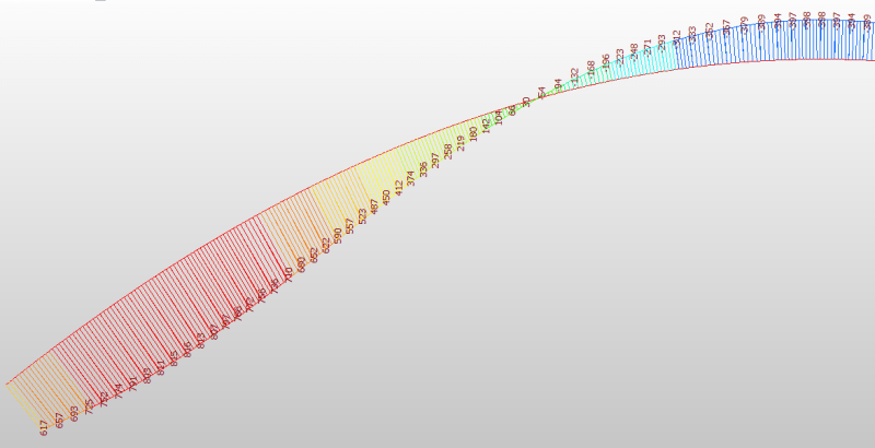
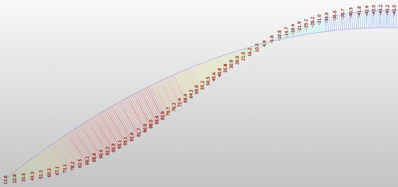
RM Bridge and Sofistik show very similar moments of the arch in all three stages,
while Midas Civil shows similar moments of the arch in the 1st and 2nd stages as those in RM Bridge and Sofistik, but very different moment in the 3rd stage.

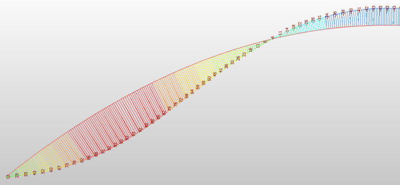
Stage 1 (The moment diagram due to self-weight is symmetrical, so only half of it is hown here)
Midas Civil
1_ligsrg.png

RM Bridge
1_aomvrm.png

Sofistik
1_e3gwxw.png


Stage 2
Midas Civil
1_nhuttd.png

RM Bridge
1_l8yvib.png

Sofistik
1_fwdnto.jpg


Stage 3
Midas Civil
1_tdhbhu.png

RM Bridge
1_ekqeim.png

Sofistik
1_fhyjud.jpg


1. Which result is correct?
2. If Midas is correct, how to fix it in RM Bridge and Sofistik; if RM Bridge and Sofistik are correct, how to fix it in Midas.
 
Replies continue below

Recommended for you

The self-weight causes the same load distribution in all three cases. You have what seems to be an arch that is uniformly loaded by its dead weight - the moment diagram will be the same for all three "stages", unless you use props or model "everything" (e.g., shrinkage, temperature variations and so on), which you did not mention.

I also wonder the same thing as "steveh49": are you sure that you´ve applied the correct boundary conditions? There should not exist any bending moment at the pinned support.

PS. This problem (a two-hinged arch, once statically indeterminate) can be solved with the force method and an excel sheet. There is no need to use FEM software, let alone three of them. If you or the client insists on FEA software, you will do just fine with one software package.
 
A few questions re your models:
[ul]
[li] Are you modelling these with creep ? If yes, what creep models are you using ? [/li]
[li] What is the time difference between the stages ? Not sure about RM bridge and Sofistik but Midas Civil uses a discrete dirichlet method of creep calculation for sequencing. This method is a bit approximate (but faster) and results can have a small error margin if time durations are very large (Midas does have internal time intervals for this - you can try tweaking them and see if it changes the results)[/li]
[/ul]

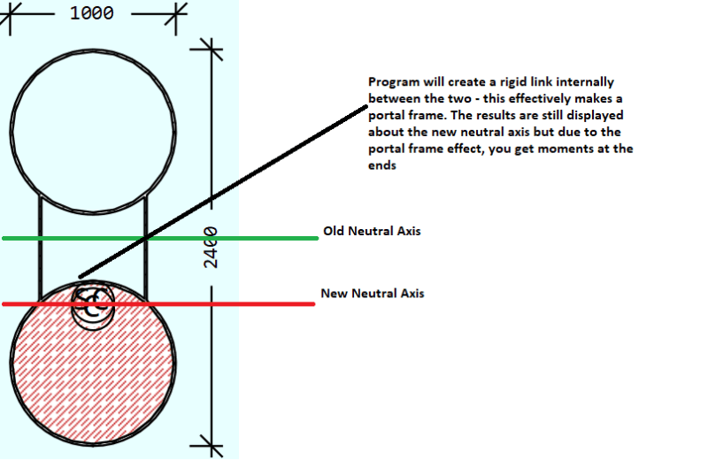
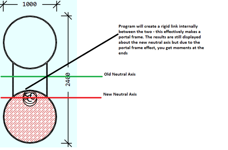
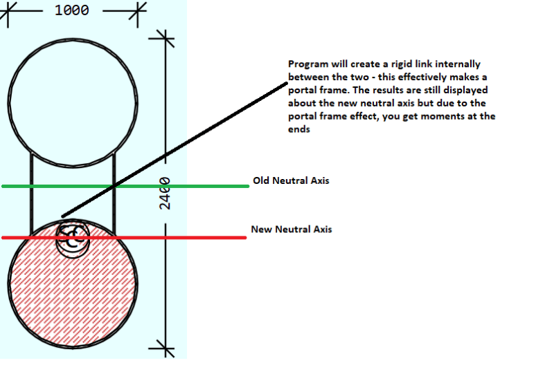
As for moments at the pin supports, I'm not surprised. Your neutral axis has shifted at stage 2 due to the introduction of concrete, but the programs will have kept the support at the original NA location (mid-point of the steel-only section). The programs internally adjust by creating a portal frame with the support at the old axis, your beam at the modified NA, and a rigid link connecting the two:

Capture_dfdind.png


What interests me is that your moments go back to zero at stage 3 for Sofistik and RM - which shouldn't happen if you're accounting for time dependent properties unless you're looking at a very long time after construction ? (concrete in the upper CHS is younger than the one in the lower CHS - I'd expect the neutral axis to remain somewhere below the section midpoint for a portion of the structure's life after lower CHS has been filled, but slowly move up to the mid point as time passes).

Edit - I noticed that the support moments in Midas Civil actually go up from stage 2 to stage 3. I'd have expected them to go down due to the neutral axis rebalancing effect I described above. Something else might be happening in the background...
 
@steveh49, @centondollar
The moment at pin support is due to
1. the distance between support and neutral axis as mentioned by FE_struct1 "Your neutral axis has shifted at stage 2 due to the introduction of concrete, but the programs will have kept the support at the original NA location"
2. the distance between mass center and stiffness center (neutral axis)

@centondollar
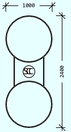
The boundary conditions are the same for all 3 softwares in all 3 stages, the support is at geometry center of the whole steel tube as shown in the stage 1, in the pic, C - geometry center, SC - shear center.
1_nqee1p_in97xs.png


@centondollar, @FE_struct1
We will consider time effects, such as creep, shrinkage and E module increasing with time in the furture. But for now, the model is under self-weight only, no time effects.

Regards
Sean
 
netsonicyxf said:
We will consider time effects, such as creep, shrinkage and E module increasing with time in the furture. But for now, the model is under self-weight only, no time effects.

If so, then the results from RM and sofistik seem ok and something weird is happening with Midas. Probably worth taking this up with Midas suppport.
 
Do they all apply the concrete load as wet concrete, then change the section afterward? Or does one (or the other two) assume the concrete is already hard when its weight is applied?

Edit: I think the support moment should be non-zero at the end, but opposite sign compared to stage 2.
 
@steveh49

The concrete were applied as hard concrete, so both weight and stiffness of the concrete were added to the structure.
 
In that case, scratch what I wrote about the moments and signs. But maybe the difference is just in the reporting conventions of the different programs.

In reality, there should be no support bending moment at the end of stage 2 as all load would be carried by the steel because the concrete was wet. The software might report some moment being the product of axial force and composite centroid offset, but there wouldn't be a corresponding linear stress profile on the section at the support. The steel would be in uniform compression (neglecting shear lag/St Venant), while the concrete would be unstressed.

So it's important to understand what the programs are reporting and make any adjustments necessary for apples to apples comparison.

Edit: is midas the one getting it right? The stage 3 composite section has its centroid at the level of the pin support, so there should be no bending moment at the support caused by stage 3. Midas is the one giving no change, just the stage 2 moment still locked in.
 
steveh49 said:
In that case, scratch what I wrote about the moments and signs. But maybe the difference is just in the reporting conventions of the different programs.
I made some tests. The span of the arch is 96m
Pin support at center of steel tube
1_qpwhu9.png

1. rise=0, beam structure, the moment at pin support is negative (top in tension)
1_tvrxlw.png

2. rise=0.1m, the moment at pin support is negative (top in tension)
1_ipfkg7.png

3. rise=0.2m, the moment at pin support is negative (top in tension)
1_fcfcws.png

4. rise=0.5m, the moment at pin support is positive (bottom in tension)
1_sbtw8p.png


Conclusion: the moment at pin support changes from negative moment to positive moment as rise increases.

steveh49 said:
Edit: is midas the one getting it right?
As for CS1 and CS2, all 3 software show similar results; but as for CS3, RM Bridge and Sofistik show similar results while Midas shows different result
FE_struct1 and I think the results from RM Bridge and Sofistik are ok, because the moment at pin support soulld be zero at CS3
 
FE_struct1 said:
As for moments at the pin supports, I'm not surprised. Your neutral axis has shifted at stage 2 due to the introduction of concrete, but the programs will have kept the support at the original NA location (mid-point of the steel-only section). The programs internally adjust by creating a portal frame with the support at the old axis, your beam at the modified NA, and a rigid link connecting the two:

According to this, only stage 2 should cause moments at the support. In stages 1 and 3, this rigid link isn't used. Midas doesn't change the support moment from stage 2 to stage 3 but the others do. Perhaps Midas is simply adding the results of the three separate analyses while the other two are making some further adjustment for the changing cross section.

These stress resultants need to be handled with care when the section is changing through the analysis. Try running the three stages as separate models rather than staged analysis.
 
I'm missing the overall question (from the OP).
 
Steveh49 might be on to something. I did a bit of digging and found this buried in midas Civil's docs:

link to relevant page:
Capture_tshu5y.png


netsonicyxf, might be worth checking to see if the accumulated stage option is checked on. If it is, then it explains midas's results.
 
steveh49 said:
Try running the three stages as separate models rather than staged analysis.
These are the moments w/o stage construction. The bottom one shows steel tube only; the middle one shows concrete put in the bottom tube.
1_brxduq.png


WARose said:
I'm missing the overall question (from the OP).
1. Which result is correct?
2. If Midas is correct, how to fix it in RM Bridge and Sofistik; if RM Bridge and Sofistik are correct, how to fix it in Midas.

FE_struct1 said:
netsonicyxf, might be worth checking to see if the accumulated stage option is checked on. If it is, then it explains midas's results.
For Midas, we use NonLinear analysis considering Accumulated Stage
Geometric nonlinear analysis is carried out with accumulated effects of the models of each construction stage. This option is used for the forward analysis of a cable stayed bridge considering large displacement.
We also tried Linear analysis considering Accumulated Stage, the distribution of moment is the same as that from nonlnear analysis, but the values are very different.
1_figfc5.png

1_mbpgci.png

1_ztogf0.png

I don't expect these big difference because the acrh is small, the effect of geometry nonliearity should be small.
We also compare results in Sofistik and RM Bridge with linear and nonlinear geometry, the difference is minimal.


For RM Bridge, we use “Accumulate Stiffness (Stage) Analysis”
The internal force state (normal forces) of previous construction stages is considered in the p-delta effect calculation. The relevant internal force state must be stored in the specified summation load case.
For Sofistik, we use CSM(Construction Stage Module) Line (Linear analysis) and CSM → TH3 (3rd order geometry nonlinear), both gives very similar results
 
I'm doing my own analysis using Strand7 to see if I can replicate either of the results. I will report back later, but I'm not clear what the end support conditions are. How can a pin support have a moment?

Doug Jenkins
Interactive Design Services
 
IDS said:
I'm doing my own analysis using Strand7 to see if I can replicate either of the results. I will report back later,
Tnank you for the help. If you need more details please let me know.

IDS said:
but I'm not clear what the end support conditions are. How can a pin support have a moment?
The end is pin support, it is at center of steel tube in all 3 stages. While at stage 2, the concrete shift the center down, so software will add a rigid arm between center and support.
1_zzv0b5.png


FE_struct1 said:
 
netsonicyxf - Thanks for that.

Here are my results:
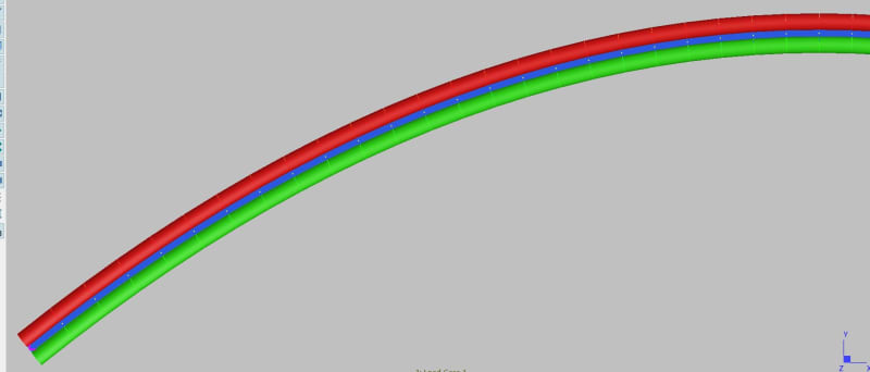
I have modelled the structure as two tubes in their actual location, connected with plate elements. The pinned supports are on the centroid of the combined steel structure, and are connected to the tubes with rigid links. The concrete is added as additional circular elements, overlying the steel tubes:
TubeArch_jqlecd.jpg


There are five load case, in three stages:
1. Steel self weight
2. Apply weight of wet concrete in lower tube
3. Connect lower hardened concrete to model
4. Apply weight of wet concrete in upper tube
5. Connect upper hardened concrete to model
Note that load cases 3 and 5 make no difference to the actions and deflections in the structure, because the weight of the concrete has already been applied, but the addition of the concrete in LC 3 does affect the distribution of the loads and deflections in LC 4.

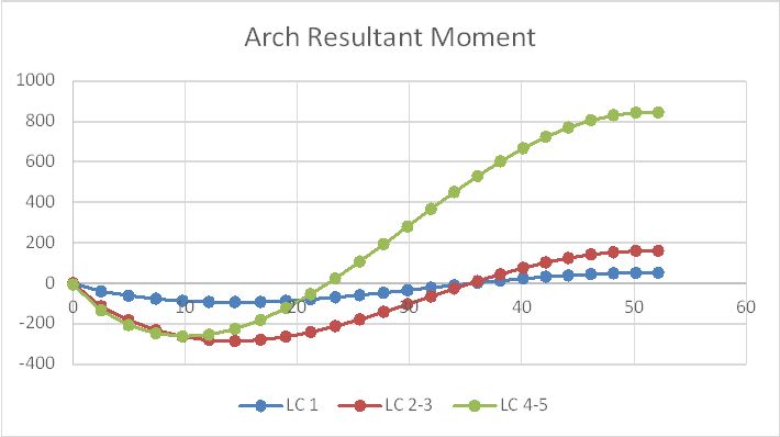
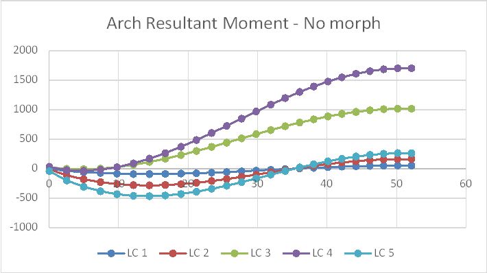
The bending moment diagram below shows the sum of steel tube member moments and axial force x offset from centre line, plus the equivalent actions in the concrete for LC 4-5. Forces in the web are ignored for simplicity for this exercise.
TubeArchMom_qo4kdd.jpg


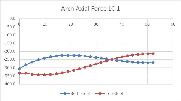
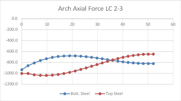
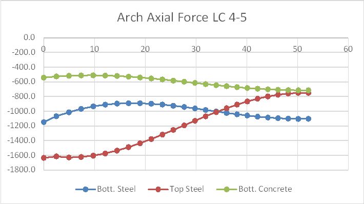
The axial load diagrams show the loads in the two tubes, plus the concrete where applicable:
TubeArchAx1_ufu87b.jpg
TubeArchAx2_audspe.jpg
TubeArchAx3_oilixv.jpg


In summary:
The LC 1 results are reasonably close to the results in the OP.
LC 2 should not have any moment at the support because the load is applied as wet concrete.
LC 3 results are the same as LC 2 because it models the hardening of the concrete, ignoring shrinkage.
My LC 4 results have no moment at the supports, because I have taken moments about the centre line of the steel section, but if you insist on using moments about the section centroid there should be a moment at the supports because the lower tube is filled with hardened concrete and the upper tube isn't.
LC 5 is the same as LC 4 because it only models the hardening of the concrete in the upper tube.

So all three analyses in the OP are wrong for their Stage 2, because they have treated the concrete as having full strength and stiffness. The results for Stage 3 showing zero moment at the supports are wrong because the section is asymmetric about the CL at that stage, and the Midas results are probably wrong as well because they are continuing from the incorrect Stage 2.

Finally I'd suggest that it is well worth the effort to spend a little extra time modelling the tubes as separate elements because it makes it much easier to see if the analysis is behaving the same as the actual structure would.


Doug Jenkins
Interactive Design Services
 
@IDS

Thank you for the analysis.
AFAIK, Strand7 has an option "Construction Sequence" for construction stage analysis. Did you use it in your analysis?
 
netsonicyxf - Yes, I used a staged analysis, and how that is set up has a large effect on the results.

Each new stage can be set to "morphed" or "unmorphed". If morphed the new elements are made to fit the deformed shape of the elements they are connected to without generating any stress, and that is the appropriate setting for wet concrete. Moment results if the concrete elements are set to unmorphed are shown below. In this case addition of the concrete elements (LC3 and LC 5) has a huge effect on the moments in the structure:

TubeArch4_jxhhbu.jpg


Doug Jenkins
Interactive Design Services
 
@IDS
IDS said:
LC 2 should not have any moment at the support because the load is applied as wet concrete.
My LC 4 results have no moment at the supports, because I have taken moments about the centre line of the steel section, but if you insist on using moments about the section centroid there should be a moment at the supports because the lower tube is filled with hardened concrete and the upper tube isn't.

1. I didn't model wet concrete in my models, so the weight and stiffness of the concrete are added together in Stage 2 and 3.
2. As FE_struct1 and I explained before, there should be moments at pin supports at Stage 2

FE_struct1 said:
 
Status
Not open for further replies.

Part and Inventory Search

Sponsor