netsonicyxf
Structural
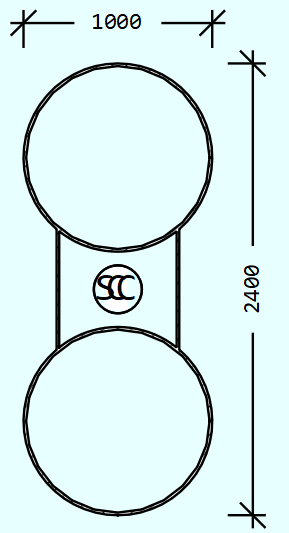
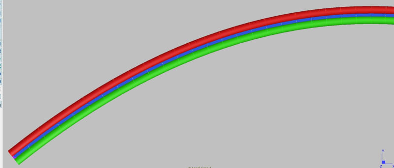
The arch has 96m in span and 19.2m in rise. It has pin support at both ends and is made of steel and concrete.
It has 3 Construction Stages
1. field installation of steel tube
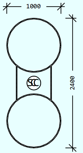
2. put concrete in the bottom steel tube
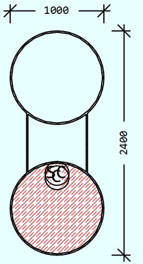
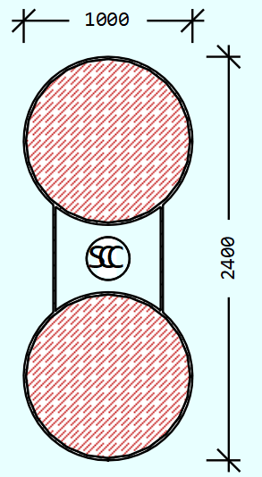
3. put concrete in the top steel tube
We use Midas Civil, RM Bridge (TDV) and Sofistik to do the construction stage analysis
We will consider time effects, such as creep, shrinkage and E module increasing with time in the furture. But for now, the model is under self-weight only, no time effects.
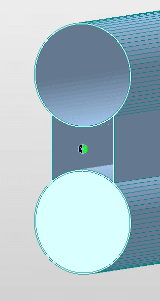
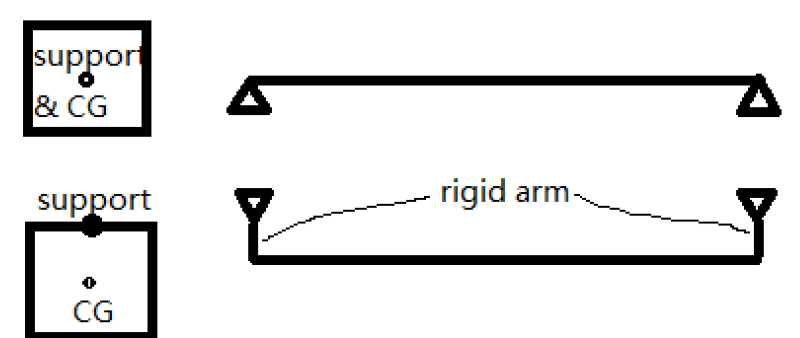
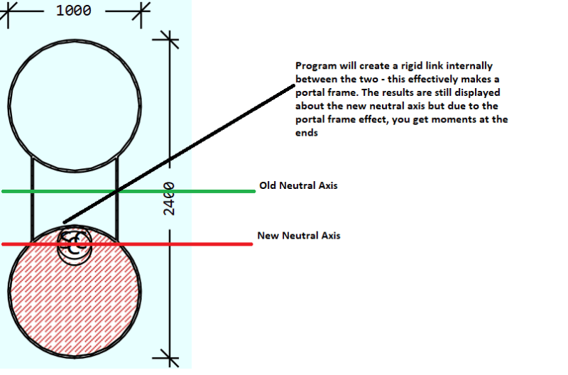
The boundary conditions are the same for all 3 softwares in all 3 stages, the support is at geometry center of the whole steel tube as shown in the stage 1.
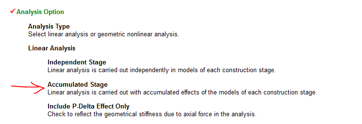
For Midas, we use NonLinear analysis considering Accumulated Stage
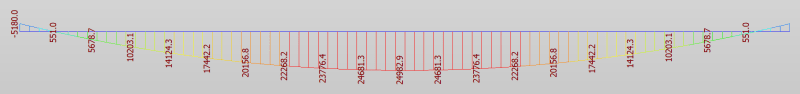
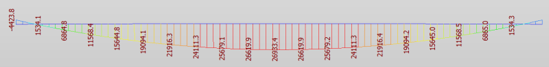
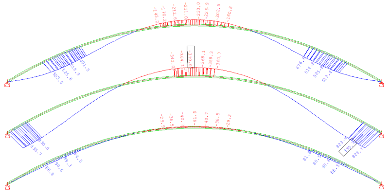
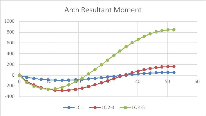
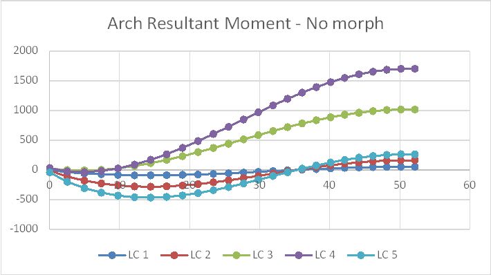
RM Bridge and Sofistik show very similar moments of the arch in all three stages,
while Midas Civil shows similar moments of the arch in the 1st and 2nd stages as those in RM Bridge and Sofistik, but very different moment in the 3rd stage.
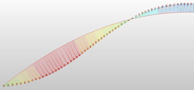
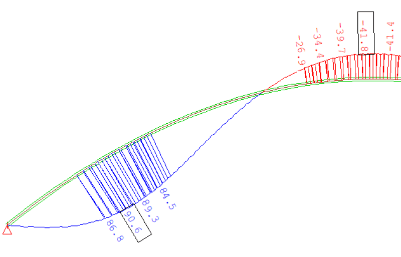
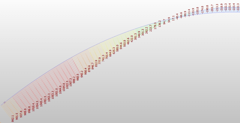
Stage 1 (The moment diagram due to self-weight is symmetrical, so only half of it is hown here)
Midas Civil
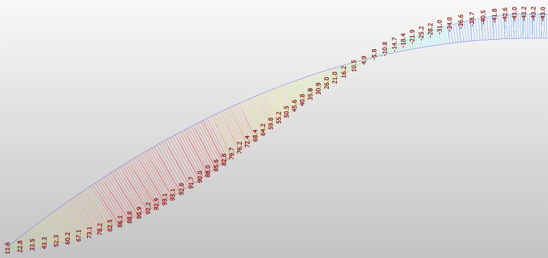
RM Bridge
Sofistik
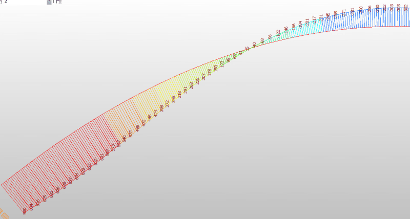
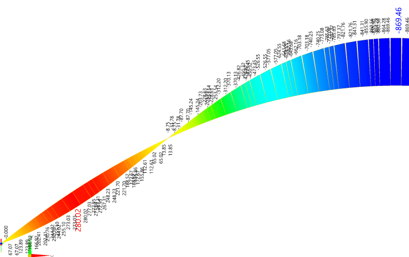
Stage 2
Midas Civil
RM Bridge
Sofistik
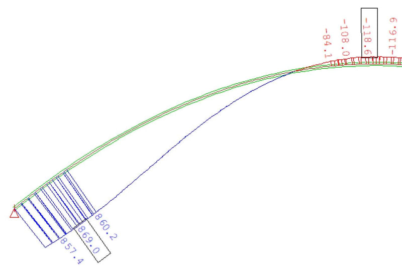
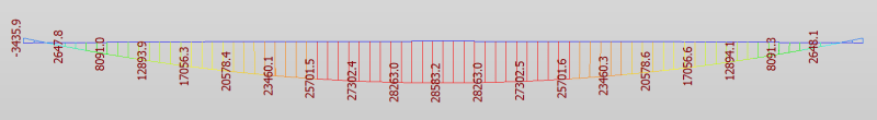
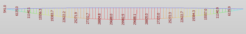
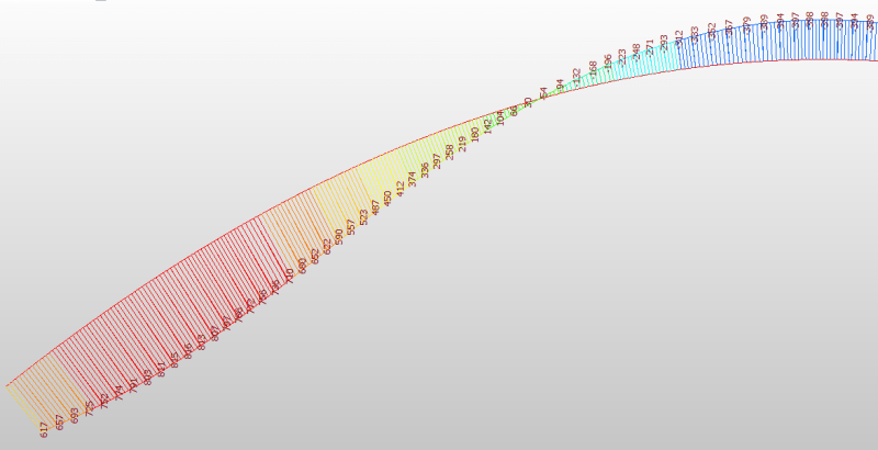
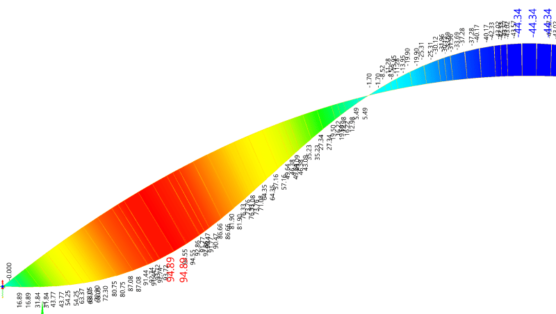
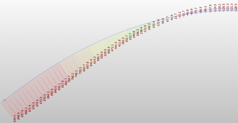
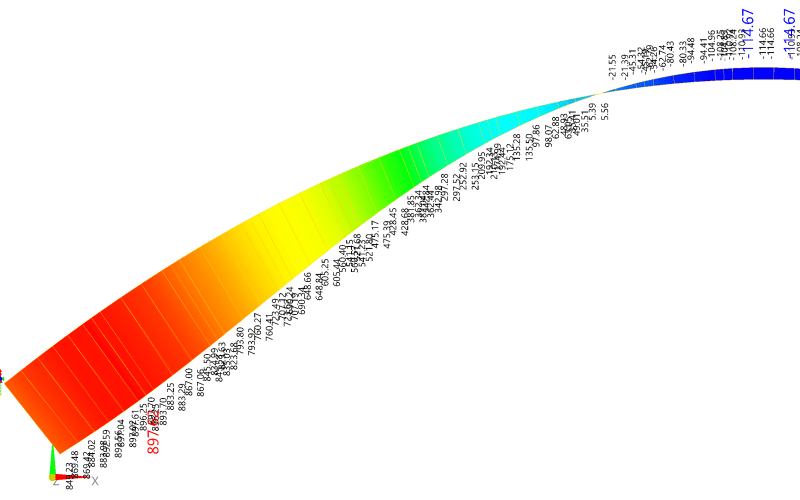
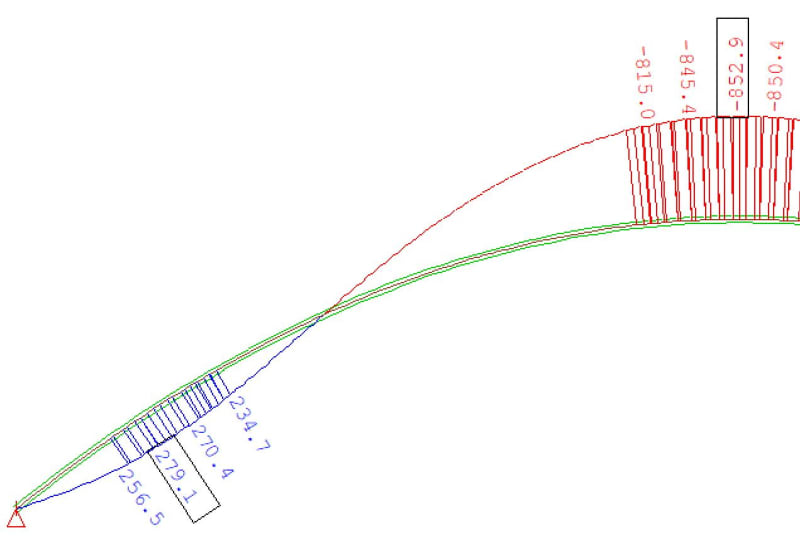
Stage 3
Midas Civil
RM Bridge
Sofistik
1. Which result is correct?
2. If Midas is correct, how to fix it in RM Bridge and Sofistik; if RM Bridge and Sofistik are correct, how to fix it in Midas.
It has 3 Construction Stages
1. field installation of steel tube
2. put concrete in the bottom steel tube
3. put concrete in the top steel tube
We use Midas Civil, RM Bridge (TDV) and Sofistik to do the construction stage analysis
We will consider time effects, such as creep, shrinkage and E module increasing with time in the furture. But for now, the model is under self-weight only, no time effects.
The boundary conditions are the same for all 3 softwares in all 3 stages, the support is at geometry center of the whole steel tube as shown in the stage 1.
For Midas, we use NonLinear analysis considering Accumulated Stage
For RM Bridge, we use “Accumulate Stiffness (Stage) Analysis”Geometric nonlinear analysis is carried out with accumulated effects of the models of each construction stage. This option is used for the forward analysis of a cable stayed bridge considering large displacement.
For Sofistik, we use CSM(Construction Stage Module) Line (Linear analysis) and CSM → TH3 (3rd order geometry nonlinear), both gives very similar resultsThe internal force state (normal forces) of previous construction stages is considered in the p-delta effect calculation. The relevant internal force state must be stored in the specified summation load case.
RM Bridge and Sofistik show very similar moments of the arch in all three stages,
while Midas Civil shows similar moments of the arch in the 1st and 2nd stages as those in RM Bridge and Sofistik, but very different moment in the 3rd stage.
Stage 1 (The moment diagram due to self-weight is symmetrical, so only half of it is hown here)
Midas Civil
RM Bridge
Sofistik
Stage 2
Midas Civil
RM Bridge
Sofistik
Stage 3
Midas Civil
RM Bridge
Sofistik
1. Which result is correct?
2. If Midas is correct, how to fix it in RM Bridge and Sofistik; if RM Bridge and Sofistik are correct, how to fix it in Midas.