Eng-Tips is the largest engineering community on the Internet

Intelligent Work Forums for Engineering Professionals

  • Congratulations waross on being selected by the Eng-Tips community for having the most helpful posts in the forums last week. Way to Go!

Composite Floor Design

Status
Not open for further replies.

CSFlanagan

Structural
Mar 17, 2006
23
US
A client has a 1980's era 2 story warehouse building. The second floor is concrete over 1 1/2" metal decking, 5" total thickness. The floor deckcing is upported by W16x26 beams spaced at 7'-6" oc, spanning 33 feet between W24x55 girders. Girders sit atop W8 columns.

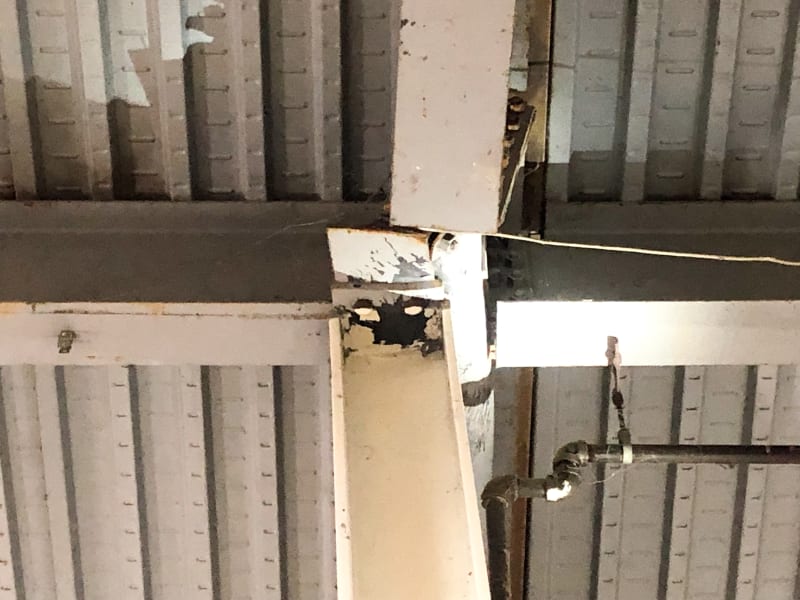
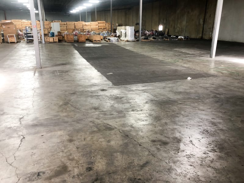
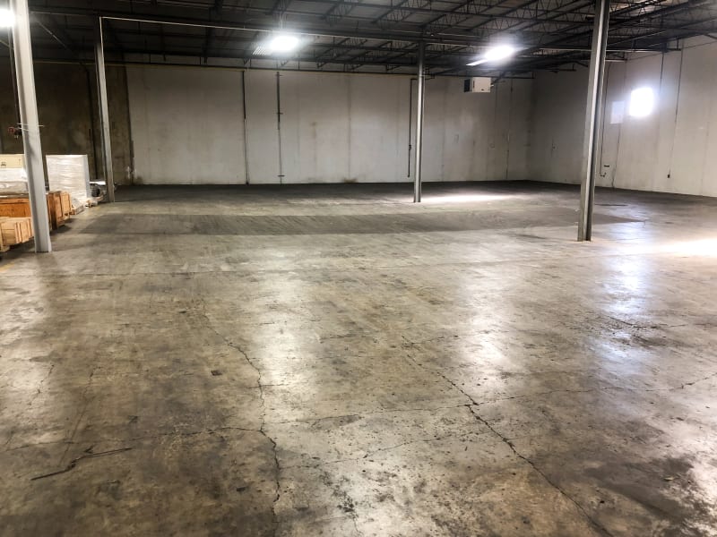
The floor was recently overloaded. The load has since been removed. The W16 floor beams have sagged permanently (approximately 2"-3" at mid-span). The W24 girder webs have buckled where they sit over top of first floor columns. (See photos attached).

Using a 67 psf dead load for the concrete floor, the W16's have very little capacity left. Even at 30 psf live load, the W16's are still failing due to total deflection exceeding l/240. And bending stress is 97% of maximum.

That doesn't make sense, so now I'm wondering if the floor was designed compositely. The decking looks like a composite deck, but I can't be sure. And 7'-6" is a long construction span for the metal decking, especially if it is a simple span.

How can I determine if the floor beams are designed compositely without going through a lot of destructive testing? There are no drawings of the existing building.

Thanks,

Scott
 
 https://files.engineering.com/getfile.aspx?folder=084a8d25-deb0-4e77-b278-1d412718b3ee&file=IMG_3108.JPG
Replies continue below

Recommended for you

You may be able to scan the slab to try to locate studs.
Though I'm not sure how a composite floor would make any difference to your substantial web buckling failure in the photo.
 
Do you have any construction details, studs on beams, etc that might indicate the beams where able to develop some composite action.

They could have been considered composite for serviceability only? In the negative moment region most engineers would ignore any composite action as its actually not that beneficial, but certainly in the positive moment regions its pretty easy to achieve and good bang for buck.

Remember in terms of deflection the deflection of the beam underside isn't so much of a concern, its the top of slab that's more critical for users and often depends on how/whether beams were propped, if beams are composite, etc. For example it's pretty typical to screed the slab level taking out any dead load deflection for unpropped construction.

Span/240 for the steel beam might be considered acceptable by some (depending on overall magnitude) if the slab is, screeded level and additional concrete dead load from the ponding is expressly allowed for. Similarly nothing wrong with designing to 97% utilisation. Not withstanding that the high utilisation might have contributed to the web buckling with a little overloading. Out of interest, how and by how much was the floor overloaded?

Makes a good case for providing lateral restraint to the lower flange at this cap plate type of connection as never seen a web buckling failure in this location before, but its something I preclude by putting load bearing stiffeners even if they are not required by design as a matter of good detailing.
 
Wow.... That girder failure is significant. They're lucky something worse didn't happen (i.e. collapse). At this point, destructive testing is probably the least of their concerns. They will have to replace all of those main girders, I would think. That'll be pretty destructive, right?
 
THAT is a buckled W24. No stiffener plates at the columns which in my book is a stupid thing to do.

I agree with all that Agent666 states above - a couple of other thoughts.
1. You can have composite deck-slabs without composite beams and visa-versa.
2. The W16 beams could have been cambered so Agent666's comment on focusing on the top surface of concrete is valid.
3. If the beams sagged under wet concrete but were screeded off level you need to take into consideration the added dead weight of that extra lens of concrete.
4. Chipping into the floor along the length of a typical W16 might be necessary to pin down the stud diameters, spacing, number, etc. You might only have to chip down a little ways to expose the heads and chip down further in one or two places to confirm the depth of concrete and stud diameter.
5. I think your approach to first back-calculating the originally intended floor capacity is important to understand what happened, what you have, and what you need to do going forward.


Check out Eng-Tips Forum's Policies here:
faq731-376
 
It's really a 2-fold issue. 1) The girder failed due to web buckling. As you can see there were no web stiffeners where the girder sits atop of the column. Apparently the though the angle clips would be sufficient, or were just not concerned with it. 2) By my calculations, the W16 floor beams can't carry much more than just the weight of the floor! Even is they used lightweight concrete, the allowable live load of the floor is only about 40 psf!
We don't know how much load was placed on the floor. The building is rented. The tenant owned up to using a "large forklift' to move "heavy boxes" and stacked them. He heard a loud "bang", so wend back out on the sagging floor to move the load back over to another floor that is slab on grade.
And yes, everyone now knows how fortunate this turned out. No loss of life and the building still stands!
 
Right now the top surface of the concrete, at least in the area of question, looks like a bowl!
I had already planned on recommending to the owner that he install web stiffeners at the other column/girder connections.
The W24x55 girder fails in bending stress and total deflection under the same loading as the floor beams. And it obviously, spectacularly fails at the column.

 
Agent666: No, there aren't any drawings available on this building.
 
CSFlanagan,

Are you assuming the top flange of the beams and girders to be braced at all, or are you assuming the full length for bending capacity analysis?
 
winelandv
If it's not composite, then the decking is still welded to the top flange for diaphragm strength. So I'm assuming the top flange is continuously braced by the deck/slab.
 
FYI, for the case of columns with beams continuously over the top, you need to be careful with the effective length, in effect if you flipped the system upside down it is like having a concentrated load on the unrestrained top (compression) flange. Most codes require the effective length to be increased when the load application is unrestrained like this. In my local code (NZ) the effective length would be increased by a factor of 1.4 to account for this destabilising effect.

The fact that the web buckled, and the mechanism of this occurring is perhaps made worse by the fact that the web can sway sideways due to this instability due to the typical 2.5% flange force requiring restraint.
 
Agent666:
Good point. The beam extends past the column only 12", so the negative moment generated is fairly small, even from the end reaction of the girder connected to it. The W16 beams extend 2/3 the depth of the W24, so they are providing some lateral stability below the CG of the girder, in the negative moment region.

McCollum-3074_l5as9a.jpg


That said, here is a picture showing that the bottom flange moved laterally almost the full width of the flange, just as you mentioned.
I've never seen web crippling to this extent before in person... only in books and some very small deformations usually caused by some local impact force or fire.

Now... how to go about fixing it!?
 
I agree that bearing stiffeners would have helped... Gee, ya think?

I think a large chunk of the deck and concrete slab will have to be removed to gain access to remove the W24 - that is toast and not worth trying to save in my opinion. The W8 column, as tweaked as it is, is quite questionable to me too. I would need to see the effect, if any on the base connection...

Need to have a lot of shoring clear to the foundation to do the removal. Maybe new temporary shoring footings too...

Going to need LOTS of pictures...

Mike McCann, PE, SE (WA)


Its seems from the second photo that the column moved over and the incoming secondary beam is now sitting on the column (supporting the whole floor). I hate to think that if that secondary beam wasn't there what would have happened, my guess is you would be looking at localised collapse and a lot more serious consequences.

Let the person who was in the forklift know they are pretty lucky that it didn't go further!
 
Looks very much like the "Station Square" failure - column/joint instability. For analysis simply apply a % of column load and bottom flange compression as a horizontal load to the bottom flange and you will see quickly, that stiffeners or bottom flange bracing is needed. "Roof Framing with Cantilever (Gerber) Girders & Open Web Joists" covers this issue quite well.
Indeed, very lucky forklift driver...
 
CSFlanigan said:
...a 1980's era 2 story warehouse building.
...W16x26 beams spaced at 7'-6" oc, spanning 33 feet...
67 psf dead load for the concrete floor... 30 psf live load..
...bending stress is 97% of maximum.

I ran the numbers using old (1980's style) ASD; it's worse than that.
Most likely A36 steel (36 ksi yield strength), not modern 50 ksi, A992 steel that I believe you are using for the 97% comparison.
Got bending stress of 30.9 ksi versus allowable 24 ksi for a W16x26 compact section... 129% of allowable.

IMHO, scrap everything and start over.

[idea]
 
Girder web crippling calcs get even worse when you recall that there is a 2nd floor column supporting the roof located directly over top the W24 and ground floor column.

For reference, the roof joists run perpendicular to the 2nd floor beams.

McCollum-3085_of3wl2.jpg

McCollum-3081_vw1h1x.jpg
 
I have never seen a any warehouse designed for less than 100 psf. 100 psf is nothing. For that reason, if calculations show the beam acting non-composite will not work for stress at least 100 psf ( I would ignore deflection) then I would have to assume the floor was originally designed composite. I would then look at current loads in the undamaged areas and see how they stack up to my non-composite calcs. If they exceed my non-composite calcs by a significant number and have no signs of distress, I am now more comfortable about the "possible composite" condition. You have a problem in the damaged area regardless, but you also need to advise the Client on other non-damaged areas. I am amazed the Client apparently has no idea what his current floor rating is. Many of my Clients are having to rate and post their elevated floors now.

They Client needs to try their best to determine what the loading was they put on the boo-boo floor. I would hard press then to recall what they stacked there. The client they were storing for knows what their pallets weighed. That gets you closer to the failure load. As already stated, it looks like a web crippling problem but what load does it take to cripple that web? Since you have to replace the beam, I would spend my current time on temporary support and damaged beam removal. At removal time, I would see how the beam is actually made.

The hardest thing you are going to have to do if there are no design drawings it to get the Client to commit to some Floor Live Load they want their building to have. I already know the answer, they want no limitation.
 
I agree with SRE. Scrap everything that was damaged and replace. The undamaged areas might be able to be increased but either way this is going to be costly for the owner.

At the very least, demo a bit of the floor above a beam to check for studs. The floor is already junk so making a few holes isn't the end of the world.

Ian Riley, PE, SE
Professional Engineer (ME, NH, VT, CT, MA, FL) Structural Engineer (IL, HI)
 
Status
Not open for further replies.

Part and Inventory Search

Sponsor

Back
Top