Eng-Tips is the largest engineering community on the Internet

Intelligent Work Forums for Engineering Professionals

Composite Profile

Status
Not open for further replies.

rsm7400

Industrial
Mar 6, 2012
52
0
0
US
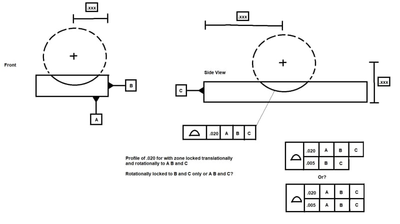
I have a SR machined into the top of a block. The bottom is datum A, the long side datum B and the short side datum C. Basic dimensions are given from each of these faces. We have profile of .020 but want to refine the shape to be within .005

For a composite tolerance I know the top line locks location and rotation. The bottom line controls rotation only. My question is, on the bottom line do I control it to A B and C or just B and C. None of the planes go thru the sphere.

Would this differ if datum B and C had been center planes with the SR having a basic of 0 to both B and C but still offset from A?

Composite_Profile_pexqch.jpg


________________________________
Ryan
3d Printing
Laser Cutting
CNC Milling
 
Replies continue below

Recommended for you

The lower segment FRTZF must repeat the PLTZF order, even though some datums might be unused.
Datum order must be repeated from top row.
 
Since the lower segment datum references control orientation of the feature and you have a sphere which has no orientation, it's not clear what you are trying to accomplish.

If you want the sphere to be more spherical, then you don't need datum feature references in the lower segment or you can use two separate segments; it really won't matter.
 
What I am trying to control: The customer print only has [prof|.xxx|A|B|C] with a pretty loose profile in the ".xxx" tolerance. For our internal manufacturing and further processing of features not show, it does not matter how the sphere is shifted up and down, but it does matter left/right and front/back. Also the form of the sphere has to be very uniform.

I've seen composite profile used in situations like this where the mating fixture or components must sit "perfect" on the surface but the location of the surface isn't as critical. The only time I've used it prior to know was with a spline shape surface that was perpendicular to another plane. This sphere example felt like composite profile would apply in a similar manner. But I do understand your comment that that a sphere has no orientation. So lets complicate things and say what if the curved surface is actually aspheric...?


________________________________
Ryan
3d Printing
Laser Cutting
CNC Milling
 
It is probably simpler to put the requirement in writing on the manufacturing process plan, which is going to describe how to fixture the part prior to the feature being made and working out the requirements for the tool set up to produce the feature.

If just writing it out isn't possible, I'd probably try three single-segment profile tolerances, one to [A|B|C] with a small tolerance and a note that deviations in the Z direction (noted by a coordinate system symbol on the drawing) are to be ignored and a second one to [A] that has a larger tolerance to limit the Z direction variations. The third would be without a datum reference and have the small form tolerance you want to maintain.
 
3DDave said:
one to [A|B|C] with a small tolerance and a note that deviations in the Z direction (noted by a coordinate system symbol on the drawing) are to be ignored
This could be accomplished by a customized datum reference frame, instead of a note.
 
Couldn't Z translation be ignored by leaving datum A out of the feature control frame?

Then two degrees of primary orientation for the datum reference frame would be driven by one of the edges and the third orientation held by the other edge - this would not match the current scheme and may be unacceptably different.

---

Why yes - the customized datum reference scheme, being used by so many, would be the first choice to ensure a phone call asking what the hell all those extra characters mean and then explaining it just meant, ignore the Z value.

But if one loves the cryptic syntax that ASME adopted, that is certainly the way to go.

How could one determine that a customized datum reference scheme would work in order to suggest it? I guess because my note was perfectly explanatory and needed no other aid to get there.
 
3DDave,
If the vendor understands that A constrains Z and what to do to release that constraint, as the note would require anyway, it takes very little extra effort to make sense of a customized DRF.

Otherwise, If degrees of freedom constraints and their override are not understood by that group, isn't it risky to trust them in the first place for manufacturing and inspection?
 
It takes getting a copy of the standard and paging through it to find a matching picture and then going back to the section the picture references to read what the standard has to say on the matter. That may involve a long walk from the shop floor to QA to get that copy of the standard when the note that explains it is right there. Or they call engineering a leave a message or send an email.

Which is to say that extra effort is more than no effort.

But you got it first go, even though what I wrote does not appear in the standard, and knew exactly what I meant.

People doing this job were trusted to do so before the customized datum reference secret handshake was invented. People walked on the Moon, created orbital telescopes to look to some of the earliest moments of the universe, sent spacecraft to exit the solar system - all without those references.
 
3DDave,
The OP's drawing has a profile of a surface callout. There were great engineering accomplishments made before profile of a surface was invented, and without it. Why don't you suggest getting rid of it as well? I can tell you, that there are still plenty of shop floor people who don't understand profile of a surface, with or without quick access to a copy of Y14.5. Isn't that an indication to you that it shouldn't be used on drawings?

Sure astronauts walked the moon before a customized datum reference frame was standardized for the engineers that documented the designs of the machines that made it possible, but how far back do you draw the line? We could as well get rid of all other tolerance callouts and replace them all with just one note: "PRODUCE AS CLOSE AS POSSIBLE TO THE NOMINAL DIMENSIONS". Very clear, and this is more or less how things were done before mass production, and mankind was doing fine back then. Why not return to that? It would surely guarantee no spending time walking from the shop floor to QA to grab a copy of the standard, and no calling or e-mailing.
 
The argument would be stronger if there was some better comparison to be made.

A single sentence to replace a complicated and rarely used symbols set put up against a concept that takes a couple of chapters is laughable.

I expect a machinist to know about datums and geometric tolerance characteristics as they appear on drawings every day.

I do not expect them to know about an arcane feature that is rarely used.

You must run your people absolutely ragged.
 
A few weeks ago on this forum, one of the members said they don't use profile of a surface because it's "highly sophisticated" and inspection can't measure it.
So they use directly toleranced dimensions instead, to locate and orient surfaces. The staff that receives the drawings in that organization won't learn the meaning of profile tolerances on their current jobs, and neither will design engineers starting to work there because it's a "GD&T callout that we don't use here".

So this is a possible approach too - avoid drawing callouts that manufacturing and inspection don't know how to work to. It doesn't matter if it's a geometric tolerance relative to a regular or a customized datum reference frame that is to be excluded from utilization. This will keep the company behind thanks to a self-feeding loop of lack of education.

Either professionals in design, manufacturing and inspection should strive to update their own and each other's knowledge, or they shouldn't.
Your approach seems to be the latter, so you should ask that 90% of all Y14.5 practices be discontinued because it results in unfair competition for those who want to be stuck in the past.
 
I suggest effective solutions when the problem requires them. This was the origin of positional tolerancing - to handle a case that rectangular coordinate tolerance zones did poorly.

Clearly the OP is already familiar with profile tolerance. Referring to some other case in some other company is not a supportive argument. Not using customized datum reference frames won't hold a company back, but getting mired in expensive schemes to manage simple requirements certainly will. My communication was so clear you understood it.

Professionals should not add burden of theoretical extensions to solve problems in arcane ways.

Why should I ask that "90% ..." be discontinued? Why the distraction?

 
A customized datum reference frame is the standardized and official way to specify what you are saying with that note. It's not considered arcane in places where it's used. And if it's not used, there is either no need for it, or there is a need and then it should be used, and it will no longer be arcane once implemented.

"Clearly the OP is already familiar with profile tolerance" - yes, but we don't know that for sure about those who will receive the OP's drawing for manufacturing and inspection. As I mentioned, for some even the profile tolerance might be "arcane". It all depends on how experienced one is with a callout. Either you communicate the requirements as standardized, or you try to adjust to whatever may or may not be "arcane" for whomever it may concern. The latter is not an "effective solution".
 
Status
Not open for further replies.
Back
Top